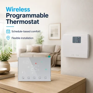
Thermostat Installation Basics: What Must Be Confirmed Before Wiring
“Can we wire this thermostat directly?”
“Maybe. But not yet.”
That is how many thermostat problems begin. The installer is ready. The wall box is open. The wires are visible. The product looks right. But the key checks are still missing. Is it for a boiler, water heating loop, fan coil unit, PICV valve, or hotel room with keycard logic? Is the system low voltage or line voltage? Does the thermostat provide dry contact, relay output, 24VDC valve output, or communication only?
If those points are not confirmed first, the wiring may look tidy on the wall but still fail in real operation. This is why thermostat installation basics are not really about connecting wires fast. They are about confirming the control logic before the first wire goes in. Honeywell Home and Resideo guidance also stress that compatibility, voltage type, and correct location must be checked before installation starts. :contentReference[oaicite:0]{index=0}
Quick Summary
Before wiring any thermostat, buyers should confirm five basics: the HVAC application, the control voltage, the power supply, the output type, and the sensor logic. A room thermostat for boiler heating is not the same as a fan coil thermostat, and a thermostat for a 24V PICV valve is not the same as a simple dry-contact thermostat. Similar wall appearance does not mean similar wiring or similar control logic.
The Checks That Prevent Most Wiring Mistakes
If the project team confirms the application first, most installation problems become much easier to avoid. The common failures are rarely caused by the screwdriver. They usually start earlier: the wrong thermostat category was selected, the voltage was assumed instead of verified, the terminals were interpreted too quickly, or the buyer focused on screen design and forgot about output logic. For projects using smart thermostat functions or communication features, early confirmation matters even more because compatibility is not universal across all HVAC systems. ENERGY STAR notes that smart thermostat savings and performance depend on the actual heating and cooling equipment, climate, and user conditions, while Honeywell guidance makes clear that low-voltage and line-voltage products are not interchangeable.

Why Thermostat Wiring Problems Usually Start Before Installation
Many buyers think thermostat installation starts when the front cover is removed. In practice, it starts when the application is identified. A thermostat controls a process, not just a temperature number. That process can be boiler demand, water heating, fan and valve control in a fan coil unit, setback logic in a hotel room, or analogue control for a PICV actuator. If the wrong process is assumed, the wiring diagram will also be wrong. Even worse, it may look correct at first glance.
This is why experienced HVAC engineers ask different questions from first-time buyers. They do not begin with “How many wires are there?” They begin with “What exactly is being controlled?” The answer changes the whole job. A boiler room thermostat may only need a dry contact. A water heating thermostat may need relay output. A fan coil thermostat may need fan-speed and valve logic. A hotel room thermostat may also need keycard input. A PICV application may require 24VDC output and sometimes Modbus integration. None of these should be guessed from product appearance alone.
For overseas sourcing, this point matters even more. Many buyers compare products from several thermostat supplier or manufacturer websites and assume that similar UI means similar function. That is a risky shortcut. In export projects, the safer method is to map the thermostat to the real field device first, then confirm the wiring logic, then confirm the model. This sequence reduces returns, field complaints, and commissioning delays.
Confirm the HVAC Application First
The first technical check is also the most important one: what kind of system will the thermostat control? This article is about thermostat installation basics, but the first “installation” decision is really a selection decision. If the HVAC application is wrong, the rest of the wiring process is built on the wrong base.
Room thermostat for boiler heating
In a boiler system, the thermostat often acts as an on/off demand device. Many projects only need dry contact control. In that case, what matters is not a fancy interface but clear switching logic, correct voltage separation, and stable demand control. If the buyer mistakenly chooses a thermostat designed for valve actuation or fan coil logic, the installation becomes more complicated without delivering any real benefit. For this kind of application, a Modbus boiler thermostat or a house thermostat for boiler and water heating is often a better fit than a generic room controller.
Thermostat for water heating systems
Water heating projects look simple, but they still require clear confirmation of output type and power supply. Some systems need a basic switching thermostat. Others need app control, communication, or stronger integration logic. Buyers should confirm whether the thermostat is only making a heating demand or also interacting with other valves, pumps, or control modules. Where the project is straightforward, a dedicated 3A water heating thermostat is often more suitable than an over-specified controller.
Thermostat for PICV or 24VDC valve control
This is a common point of confusion in commercial projects. A buyer may assume that a standard relay thermostat can control any room temperature device. That is not always true. If the field device is a PICV actuator that expects 24VDC output logic, the thermostat must match that control method. If the project also needs communication, that should be confirmed before wiring drawings are finalised. For these cases, a 24VDC PICV thermostat with Modbus is usually the right direction.
Hotel room thermostat with keycard logic
Hotel HVAC projects add another layer. The thermostat may need to react to occupancy or keycard input, not only room temperature. In those jobs, a normal room thermostat can be wired correctly and still be operationally wrong because it cannot support the required energy-saving logic. A dedicated keycard HVAC thermostat is often the safer option for 2-pipe or 4-pipe hotel rooms.
The practical lesson is simple. Before any installer asks where R, W, Y, G, COM, NO, or NC should go, the buyer should first confirm the application category. That single check removes a large share of preventable mistakes.
Low Voltage or Line Voltage? This Must Be Clear Before Any Wiring
Once the HVAC application is clear, the next checkpoint is voltage type. Many thermostat wiring mistakes happen because the installer assumes the product is low voltage when the field condition is actually line voltage, or the other way around. Honeywell Home states clearly that if the system shows 120 Vac or 240 Vac, a low-voltage thermostat will not work; line-voltage systems require a line-voltage thermostat. Honeywell also notes that thick black or red wires are common signs of line-voltage wiring. :contentReference[oaicite:2]{index=2}
| Check Item | Low-Voltage Thermostat | Line-Voltage Thermostat |
|---|---|---|
| Typical control voltage | 24 VAC | 120–240 VAC |
| Typical use | Boiler, central HVAC, water heating, many room thermostat projects | Electric baseboard and some direct electric heating systems |
| Main risk | Terminal mismatch or missing common power | Serious incompatibility and safety risk if low-voltage thermostat is used |
| Smart thermostat compatibility | Often possible, but still system-dependent | Often limited or not supported by low-voltage models |
For buyers comparing a smart thermostat or room thermostat across different markets, this is not a minor detail. It is a selection barrier. If the voltage category is wrong, the product is wrong. That should be treated as a stop point, not as something to “solve later on site.”

Confirm the Power Supply and Terminal Functions
After confirming the application and voltage type, the next check is power. The thermostat may be powered by 24VAC, 95–240VAC, batteries, or a dedicated supply from the system controller. This affects both installation and long-term stability. Some smart thermostat products require continuous power. Some can work with batteries but still perform better with a common wire. Honeywell Home’s installation support highlights C-wire checking as part of thermostat wiring preparation. :contentReference[oaicite:3]{index=3}
At the same time, terminal labels should never be interpreted only by habit. A terminal marked COM may mean common in one context and communication in another. A room thermostat for boiler heating may use NO/COM dry contact, while a fan coil thermostat may use dedicated fan-speed outputs and valve outputs. A 24VDC output thermostat for PICV control is different again. Installers should read the exact wiring diagram for the actual model, not rely on memory from a different thermostat manufacturer or older project.
Good practice here is simple. Before wiring, make a small terminal confirmation sheet with four columns: terminal name, terminal function, connected field device, and expected control result. This is a low-cost habit that avoids expensive miswiring. It is especially useful when the site team, purchasing team, and supplier are in different countries.
Match the Output Type to the Controlled Device
This is one of the most overlooked parts of thermostat installation basics. Many buyers ask whether the thermostat is “for heating” or “for cooling,” but they do not ask how the thermostat outputs the command. That is the wrong question sequence. The first question should be: what output does the controlled device expect?
Dry contact output
Dry contact is common in boiler demand control. The thermostat acts as a switch. If the project only needs demand on/off, then a simple and stable dry-contact thermostat is often enough. Adding unnecessary control layers can make installation harder without solving any real project need.
Relay output
Relay output is often used in water heating or switching applications. Here, the key checks are contact rating, power compatibility, and whether the thermostat is directly switching the load or only sending a control instruction to another device. Do not assume that all “heating thermostats” behave the same way.
24VDC output
Commercial room control projects with PICV actuators often need a thermostat that sends a proper control output to the valve or actuator. If the output type is wrong, the system may not modulate correctly or may not respond at all. This is why PICV projects should be checked early, not after material arrives on site.
Communication and integration output
If the project needs Modbus, BMS integration, or hotel control logic, then communication is not just an optional extra. It changes the selection process. Some buyers think that WiFi control and Modbus integration are similar because both seem “smart.” They are not the same. WiFi is typically for app-side user control. Modbus is usually for system integration, monitoring, or supervisory control. If the project needs BMS visibility, register logic should be confirmed before order placement, not during commissioning.
For overseas buyers, this section is where a good thermostat supplier adds value. A good supplier does not only send a quotation. They help map the output logic to the real system. That is often the difference between a smooth project and a delayed one.
Sensor Logic Must Be Confirmed Before the Wiring Diagram Is Final
A thermostat does not only switch output. It decides when to switch output. That decision depends on sensing. If the sensing logic is unclear, the wiring logic may also be wrong. Different projects may use a built-in room sensor, a remote air sensor, a floor sensor, or a return-water sensor. Each one changes the practical installation method.
Resideo installation documents advise placing sensors on inside walls around 1.5 metres, or about 5 feet, above the floor, with good air circulation and away from drafts, doors, direct sun, and similar disturbances. The same guidance warns against poor locations such as dead air spots or areas above vents. Those placement rules are not cosmetic. They directly affect temperature reading and therefore control performance.
For underfloor or surface temperature protection applications, floor sensor position matters as much as the thermostat itself. If the sensor is placed badly, the thermostat may protect the wrong point or react too slowly. For hydronic control, remote or return sensing may matter more than room sensing in some specific strategies. This is why the buyer should confirm the intended sensing method before the installer closes the wall box and finalises wiring.
In simple terms: if the thermostat sees the wrong temperature, it will make the wrong decision. Clean wiring cannot fix bad sensing.
Choose the Right Installation Location Before Wiring Starts
Thermostat installation basics also include location. This part is often treated as a small field detail, but it should be treated as a control-quality issue. Resideo guidance recommends installation on an inside wall, about 5 feet above the floor, with good air circulation, and away from direct sunlight, air drafts, dead air spaces, and concealed heat sources. :contentReference[oaicite:5]{index=5}
Why does that matter? Because the thermostat is only as good as the conditions it measures. A thermostat behind a door, near an air outlet, or hit by sunlight may read a room condition that is not representative of the actual occupied zone. The result is poor comfort and poor energy performance. In a hotel room, this can cause guest complaints. In a residential room, it can cause overheating or underheating. In a commercial control project, it can make the whole system seem unstable even when the wiring is technically correct.
This point also connects with energy performance. The U.S. Department of Energy says that simply turning the thermostat back 7°–10°F for eight hours a day can save as much as 10% a year on heating and cooling, while ENERGY STAR states that the average certified smart thermostat saves about 8% of heating and cooling bills, or about $50 per year. Those savings depend on meaningful control, and meaningful control depends on correct sensing and location.
If the Project Needs Modbus, WiFi, or Hotel Control, Confirm Integration Logic Early
Not every thermostat project is a basic stand-alone job. Many current projects need some form of integration. That may be app-based control, Modbus communication, hotel occupancy logic, or energy-saving setback. These requirements should be confirmed before wiring, because they change both product selection and site planning.
Take hotel applications as an example. A standard room thermostat may control temperature perfectly well, but if the room also needs keycard-linked setback, that thermostat may still be the wrong choice. The same applies to commercial room control. A thermostat that works as a local display unit is not automatically a good Modbus thermostat for BMS integration.
For this reason, buyers should confirm four integration questions early:
- Is the thermostat stand-alone, app-controlled, or BMS-integrated?
- Does the project need only local switching, or also communication feedback?
- If Modbus is required, what data points matter most?
- If the site is a hotel, does the thermostat need keycard or occupancy logic?
These are not advanced questions. They are basic installation questions in modern projects. The more integrated the job is, the more important they become.
A Practical Pre-Wiring Checklist for Overseas Buyers
The most useful way to apply thermostat installation basics is to use a short checklist before the installer starts. This is especially helpful for importers, project buyers, and OEM customers working across time zones.
- Confirm the HVAC application. Boiler, water heating, fan coil, PICV, hotel room, or other?
- Confirm voltage type. Is it low voltage or line voltage?
- Confirm power supply. 24VAC, 95–240VAC, battery, controller-fed, or other?
- Confirm terminal logic. Do not assume labels mean the same thing across models.
- Confirm output type. Dry contact, relay, 24VDC output, or communication?
- Confirm sensor logic. Built-in, remote, floor, return-water, or combined?
- Confirm location. Inside wall, correct height, no direct sun, no strong draft.
- Confirm integration requirement. WiFi, Modbus, BMS, keycard, or stand-alone?
- Confirm the correct wiring diagram revision. Use the exact drawing for the exact model.
- Confirm test sequence after installation. Heating call, cooling call, valve action, fan speed, communication, and sensor reading.
If a buyer uses this checklist consistently, many project issues can be prevented before they appear. That is why this article focuses on confirmation before wiring, not wiring after confusion.
Expert Commentary & Analysis
From a market point of view, the thermostat category is moving away from simple wall control and toward system-specific control. Buyers now compare smart thermostat features, room thermostat appearance, app functions, Modbus integration, hotel energy saving, and even energy reporting. That makes pre-wiring confirmation more important than it used to be.
Industry guidance supports that direction. ENERGY STAR explains that smart thermostat performance depends on the actual heating and cooling system and user conditions, not on a generic claim alone. The U.S. Department of Energy also points to the value of correct thermostat operation and setback strategy for saving energy. In practical terms, that means the control method has to match the HVAC reality. A product that looks advanced but is not compatible with the real system will not deliver the expected result. :contentReference[oaicite:7]{index=7}
In export manufacturing and project supply, this is also where product-page content should help the buyer make the right decision early. Clear content about system type, voltage, output logic, and application fit is not only good SEO. It reduces technical misunderstanding. That is especially true for pages like boiler thermostat with Modbus, house thermostat for water heating and boiler heating, and 24VDC PICV thermostat with Modbus, where the buyer often needs to confirm logic before discussing price.
Real-World Checks: Three Common Project Scenarios
Case 1: Boiler replacement project
A buyer wants to replace an old room thermostat in a boiler heating system. The old unit has only simple switching logic. The new thermostat looks better and adds communication. The project team is ready to wire it, but one question changes the whole job: does the boiler only need dry contact demand, or does the new thermostat also need stable power and dedicated communication setup? If that is not confirmed before wiring, the replacement can turn a simple job into a troubleshooting exercise.
Case 2: Hotel guest room retrofit
A hotel project orders room thermostats for guest-room refurbishment. The initial idea is simple temperature control. Later, the operator explains that keycard-linked energy saving is also required. At that point, the selection logic changes. A normal room thermostat may still mount on the wall, but it is not the right control device. For this reason, hotel projects should confirm occupancy logic from the beginning. A product such as a keycard HVAC thermostat for 2-pipe or 4-pipe use is usually more suitable when energy-saving room control is part of the scope.
Case 3: PICV room control in a commercial project
A commercial buyer needs room-level control for a PICV-based solution. At first, the team assumes any thermostat with heating function should work. After review, they find that the valve actuator needs 24VDC output and the project also wants Modbus visibility. That discovery changes the whole wiring plan. In this case, a dedicated PICV thermostat with Modbus is usually a better choice than a basic relay thermostat.
These examples show the same pattern. The correct thermostat is usually not decided by display style. It is decided by control logic.
Scientific Data and What It Means in Practice
Scientific and institutional data do not replace field checking, but they help explain why correct thermostat confirmation matters. The U.S. Department of Energy says thermostat setback can save as much as 10% per year on heating and cooling under the right conditions. ENERGY STAR says the average certified smart thermostat saves about 8% of heating and cooling bills, or roughly $50 a year. These are useful benchmarks, but they assume that the thermostat is compatible, properly installed, and actually controlling the right system in the right way.

That point is important for buyers reading high-exposure blogs or supplier product pages. Energy-saving potential is real, but it is not automatic. The control chain still has to be correct: correct application, correct sensor position, correct output, correct wiring, and correct commissioning. If one of those is wrong, the expected performance may never appear.
Common Mistakes Buyers Should Avoid
- Choosing a thermostat by appearance instead of by control logic.
- Assuming all room thermostat products are low voltage.
- Ignoring power supply requirements until the site visit.
- Using an old wiring habit on a new thermostat model.
- Confusing WiFi control with Modbus integration.
- Ignoring keycard or occupancy requirements in hotel projects.
- Finalising the wiring diagram before confirming sensor strategy.
- Installing the thermostat in a poor sensing location.
If a buyer avoids these mistakes, the project usually becomes simpler, not more complex. That is the real purpose of installation basics.
Frequently Asked Questions
1. What should be confirmed before wiring a thermostat?
Before wiring a thermostat, the buyer should confirm the HVAC application, voltage type, power supply, output type, terminal logic, sensor method, installation location, and any communication or keycard requirement. These checks should be completed before the installer follows the wiring diagram.
2. Can any room thermostat work with any heating system?
No. A room thermostat must match the actual heating or control system. Boiler heating, water heating, fan coil control, PICV valve control, and hotel keycard HVAC projects may all require different thermostat logic, outputs, or wiring methods.
3. How do I know whether my thermostat is low voltage or line voltage?
The safest method is to check the system specification and the thermostat documentation. Honeywell Home guidance notes that 120 Vac or 240 Vac indicates a line-voltage system, while many central HVAC and boiler controls are 24 Vac low-voltage systems. Do not guess based only on appearance.
4. Do I need a C wire for a smart thermostat?
Many smart thermostat models need continuous power and may require a C wire or an equivalent power solution. The exact answer depends on the thermostat design and the HVAC system. This should be checked before installation, not after the wall plate is mounted.
5. Can a thermostat be wired correctly but still control the system incorrectly?
Yes. That happens when the wiring is neat but the thermostat is wrong for the application, voltage, output type, sensor strategy, or control requirement. Correct wiring only works when the control logic was confirmed first.
Before wiring any thermostat, the real job is not connecting the terminals quickly. It is confirming the system, voltage, output, sensing method, and control target first. Once those points are clear, wiring becomes much more predictable. If they are not clear, even a clean installation can still fail in real use.
References / Sources
- U.S. Department of Energy — Programmable Thermostats.
- ENERGY STAR — Smart Thermostats FAQ.
- ENERGY STAR — Smart Thermostat Best Practices Guide.
- Honeywell Home — How to Wire a Thermostat | Thermostat Wiring Diagram.
- Honeywell Home — Find Thermostat Voltage.
- Resideo — TH141-HC-28 Installation Instructions.
- Resideo — TH110-DP-P / TL8230 Installation Guidance.
- Resideo — T10 & T10+ Pro Smart Thermostat with RedLINK Installation Guide.
- U.S. Department of Energy — Operating and Maintaining Your Heat Pump.
- ENERGY STAR — Technical Bulletin: ENERGY STAR Certified Smart Thermostats.