Quick Summary
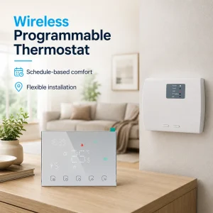
A wireless thermostat must be matched with the right sensor, relay and output type before it is used in a project. Many customer complaints come from wrong sensor position, wrong receiver output, relay overload, dry contact misunderstanding or valve logic mismatch. A wireless room thermostat should be checked as a complete control chain, from room sensing to receiver switching and HVAC equipment response. Correct matching reduces installation failure, after-sales pressure and brand risk.
“The room temperature looks wrong. Is the sensor bad?”
“The thermostat shows heating, but the equipment does not start.”
“The receiver relay failed after a short time. Did we choose the wrong model?”
These are common questions in wireless thermostat projects. Many buyers first think the product has a quality problem. But in many real cases, the root cause is wrong matching.
A wireless thermostat does not work alone. It depends on the sensor, receiver, relay, output type and HVAC equipment. If one part does not match the system, the whole control result becomes unstable.
This guide explains how to match a wireless room thermostat with the right sensor, relay and output type. It is written for overseas buyers, HVAC contractors, OEM buyers and distributors who want fewer complaints and safer product selection.
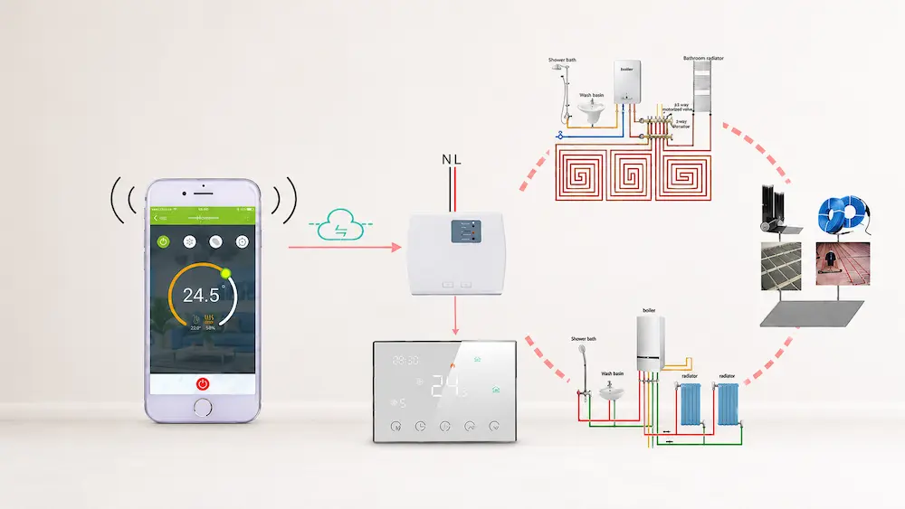
Start with the Full Control Chain
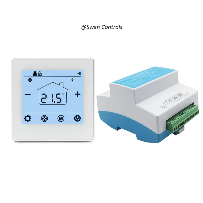
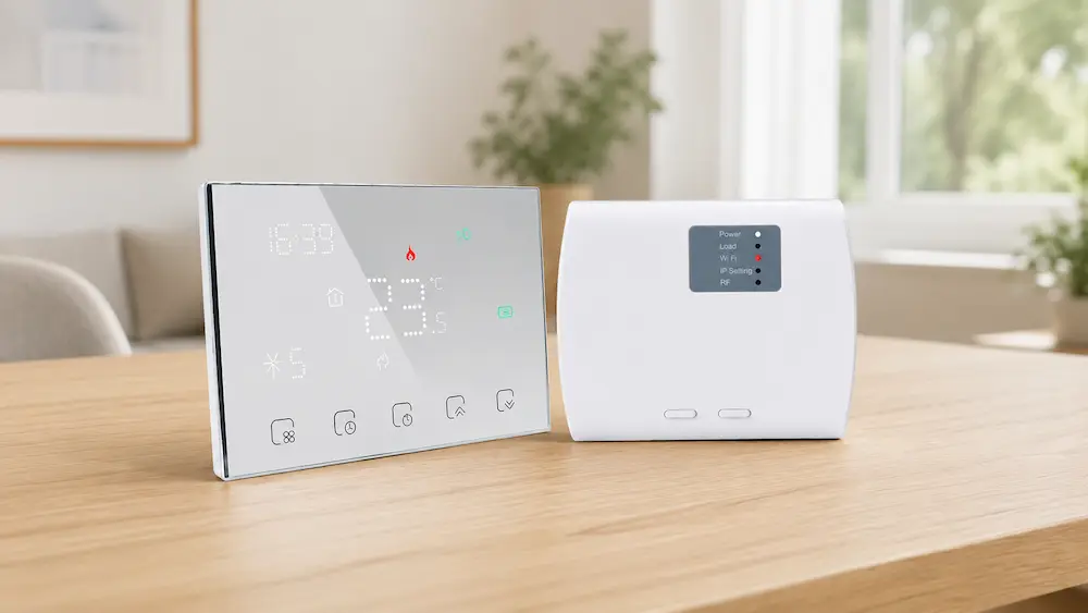
Before checking any single component, buyers should understand the full control chain. A wireless thermostat system usually has three stages.
- The room unit senses temperature.
- The wireless signal sends demand to the receiver.
- The receiver output controls the HVAC equipment.
If the room unit reads temperature incorrectly, the control starts from the wrong data. If the wireless receiver gets the command but has the wrong output type, the equipment may not respond. If the relay is too weak for the load, it may fail early.
This is why the thermostat should be matched as a system, not as a single display product.
Common pain points caused by poor matching include:
- Room temperature feels different from display value
- Boiler does not start after heating demand
- Valve opens in the wrong condition
- Receiver relay burns or sticks
- Fan or pump runs at the wrong time
- Installer cannot confirm wiring logic
- Customer blames the thermostat brand
The solution is to check sensor type, relay capacity and output logic before confirming samples or mass orders.
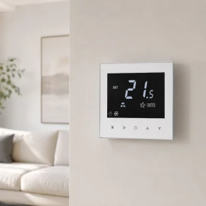
Match the Sensor with the Real Temperature Problem
The sensor decides what the thermostat “believes” about the room. If the sensor is wrong, the output will also be wrong.
Most wireless room thermostats use a built-in room sensor. This is suitable for many residential and light commercial spaces. But some projects need an external sensor or remote sensor.
Built-in sensors are suitable when:
- The thermostat is installed in a normal room position
- There is no strong sunlight on the thermostat
- There is no direct airflow from a vent
- The wall temperature is close to room temperature
- The user wants simple installation
External sensors are more suitable when:
- The thermostat must be placed away from the best sensing point
- The room has uneven temperature distribution
- The system controls floor heating
- The sensor needs to measure another location
- The project needs more stable measurement
Customer pain point: “The display says 23°C, but the room feels cold.”
Possible cause: the sensor is affected by sunlight, wall heat or airflow. The sensor may not be defective. It may be installed in the wrong position or be the wrong type for the project.
Solution: confirm whether a built-in sensor is enough. For difficult rooms, choose a wireless thermostat model that supports an external sensor or calibration.
Check Sensor Accuracy and Calibration Range
Sensor accuracy affects comfort directly. A small difference may be acceptable. A large difference creates complaints.
For normal comfort control, buyers should check the sensor accuracy, display resolution and calibration function. A common accuracy range for room thermostats is around ±0.5°C to ±1.0°C, depending on model design.
Calibration is useful when the displayed temperature is slightly different from a reference thermometer. But calibration should not be used to hide a poor installation position.
Good sensor matching should include:
- Clear temperature accuracy value
- Reasonable display resolution
- Calibration or temperature compensation function
- External sensor option if needed
- Sensor failure warning if supported
Customer pain point: “Different rooms use the same thermostat, but temperatures feel uneven.”
Possible cause: sensor placement, calibration differences or wall conditions may be different between rooms.
Solution: provide installation guidance and calibration instructions. For project buyers, test several samples in the same room before bulk order. This helps check product consistency.
Match Relay Rating with the Real Load
The relay is a small internal part, but it has a large effect on reliability. It is responsible for switching the load.
Many buyers only ask whether the thermostat can control heating or cooling. They do not ask whether the relay can handle the real load. This is risky.
Relay matching should include:
- Rated current
- Rated voltage
- Load type
- Resistive or inductive load
- Mechanical life
- Electrical life
- Need for external contactor
A resistive load is usually easier to switch. An inductive load, such as some motors, pumps or actuators, can stress relay contacts more. Startup current may also be higher than normal running current.
Customer pain point: “The receiver worked during sample test, but failed after installation.”
Possible cause: the relay may have been connected to a load that was too high or unsuitable.
Solution: compare the relay rating with the real equipment load. For higher load systems, use the wireless thermostat receiver to control an external relay or contactor instead of switching the main load directly.
Understand Dry Contact and Powered Output
This is one of the most common causes of wrong control.
Dry contact output works like a simple switch. It does not provide voltage. Many boiler systems require dry contact control. The receiver only opens or closes the circuit.
Powered output is different. It sends voltage to the connected load. This may be used for valve actuators, pumps or other loads, depending on the system.
| Output Type | How It Works | Common Application |
|---|---|---|
| Dry contact | Switches circuit without supplying voltage | Boiler heating enable signal |
| Powered relay output | Supplies voltage to the load | Valve or heating load control |
| Low-voltage output | Controls low-voltage equipment | 24V control systems |
| Line-voltage output | Switches mains voltage load | Some 110V or 230V applications |
Customer pain point: “The boiler does not start after wiring.”
Possible cause: the boiler needs dry contact, but the selected receiver output is not correct. Or the installer connected powered output where dry contact is required.
Solution: always ask for the HVAC equipment wiring diagram and the receiver wiring diagram. Confirm whether the equipment needs voltage or only a switch signal.
Match Normally Open and Normally Closed Logic
Output logic can also cause wrong control. Some systems require normally open logic. Some systems require normally closed logic.
Normally open means the circuit is open when there is no demand. It closes when the thermostat calls for heating or cooling. Normally closed means the circuit is closed in normal condition and opens during control action.
Common matching checks include:
- Does the boiler need NO or NC contact?
- Does the valve actuator open with power or close with power?
- Does the project require fail-safe logic?
- What happens during power loss?
- Does the receiver support both NO and NC terminals?
Customer pain point: “The valve works in reverse. It opens when it should close.”
Possible cause: output logic does not match the actuator. The thermostat may be working, but the connected equipment logic is opposite.
Solution: check the actuator type before wiring. Confirm normally open, normally closed or spring-return logic. Choose a receiver with suitable terminals or adjustable output logic.
Match Output Type with Boiler Heating
Boiler heating is one of the most common applications for wireless thermostats. It is also one of the easiest places to make a matching mistake.
Many boilers need a dry contact signal. The receiver should behave like a switch. It should not send the wrong voltage into the boiler control terminal.
Before using a wireless thermostat for boiler heating, confirm:
- Does the boiler require dry contact?
- What terminal should the receiver connect to?
- Does the boiler have voltage on its control terminal?
- Is polarity important?
- Does the boiler manual show thermostat connection?
- Is the receiver relay rating suitable?
For OEM buyers, boiler compatibility should be clearly explained in product documents. If the product is sold as a boiler wireless thermostat, the receiver output must be clear.
Customer pain point: “Installers in our market are confused by the wiring.”
Solution: provide a simple boiler wiring example. Use clear terminal names. Add dry contact explanation in the manual. This reduces after-sales questions.
Match Output Type with Valve or Actuator Control
Valve control requires different checks from boiler control. The buyer must know the valve actuator voltage and control logic.
Some actuators are 230V. Some are 24V. Some are normally closed. Some are normally open. Some need two-wire control. Others need three-wire control.
Before matching a wireless thermostat with valve control, confirm:
- Valve actuator voltage
- Normally open or normally closed type
- Two-wire or three-wire actuator
- Power open or spring return logic
- Relay output voltage
- Load current
- Whether an external relay is required
Customer pain point: “The room is always too hot because the valve does not close.”
Possible cause: the receiver output does not match the valve actuator logic.
Solution: match the output type to the actuator before ordering. For project supply, test one complete set: thermostat, receiver, valve and power supply.
Match Output Type with Fan Coil or Multi-Output Systems
Fan coil systems can be more complex. A simple wireless thermostat may not support all FCU functions.
Some fan coil systems need valve control only. Some need fan speed control. Some need heating and cooling mode. Some need 2-pipe or 4-pipe logic.
Before using a wireless thermostat in a fan coil system, confirm:
- Does the thermostat support FCU control?
- Does the receiver support fan output?
- Are low, medium and high fan speeds needed?
- Is valve output required?
- Is heating and cooling mode required?
- Is the system 2-pipe or 4-pipe?
- Does the relay rating match the fan load?
Customer pain point: “The wireless room thermostat controls temperature, but the fan does not respond.”
Possible cause: the product is designed for simple heating control, not FCU control.
Solution: do not assume every wireless thermostat can control fan coil units. Ask for an FCU wiring diagram and receiver output details before ordering.
Related product categories for project buyers:
Electric Underfloor Thermostat
Scientific Data
The data below gives practical reference values for matching wireless thermostats with sensors, relays and output types. These values help buyers judge product suitability before samples or bulk orders. Actual performance depends on product design, HVAC equipment, load type, installation and wiring quality.
| Matching Item | Typical Reference Value | Buyer Meaning |
|---|---|---|
| Room sensor accuracy | ±0.5°C to ±1.0°C | Supports stable comfort control. |
| Poor placement error | 2°C to 3°C possible | Wrong sensor position causes false control. |
| Calibration range | ±3°C to ±5°C by model | Useful for small field adjustment. |
| Common relay rating range | 3A to 16A by model | Must match boiler, valve, fan or heating load. |
| Relay mechanical life | 100,000 to 1,000,000 cycles | Higher life reduces receiver failure risk. |
| Indoor wireless range | 20 m to 30 m typical | Important when receiver is far from room unit. |
| Wall signal reduction | 30% to 70% possible | Signal test should be done in real rooms. |
| Common control voltage | 24V, 110V, 220–240V | Must match local system and receiver design. |
| Quiet room fan noise reference | 30 dB to 45 dB | Relevant when output controls FCU fan operation. |
| Sample test quantity | 3 to 10 units recommended | Helps check consistency before bulk order. |
These values show why matching should be checked before installation. A sensor may have good accuracy, but poor placement can still create a 2°C to 3°C error. A relay may work in a short test, but fail early if it controls the wrong load.
Relay rating should be checked against the real system. For inductive loads or higher loads, an external contactor may be safer. For boiler dry contact control, buyers should confirm that the receiver does not send unwanted voltage.
Wireless range also affects output stability. If the receiver is too far from the room unit, control may become intermittent. The result may look like a relay or thermostat problem, but the real cause is weak communication.
For buyers, the practical lesson is clear. Test the complete chain: sensor reading, wireless signal, receiver output and HVAC equipment response.
Sample Testing Should Include the Real Load
Many buyers test only the thermostat display and pairing. This is not enough.
A proper sample test should include the actual output and load. If the product will control a boiler, test with boiler control logic. If it will control a valve, test with the valve actuator. If it will control a fan coil unit, test the fan and valve outputs.
Sample testing checklist:
- Sensor reading compared with a reference thermometer
- Calibration function test
- Wireless range test
- Receiver pairing test
- Dry contact output test
- Powered output test, if applicable
- NO and NC logic test
- Relay load test
- HVAC equipment start and stop test
- Power loss recovery test
Customer pain point: “The sample worked in the office, but failed at the site.”
Solution: test the product with the real system or a realistic test rig. Desk testing is useful, but it does not prove full compatibility.
Documentation Must Explain Matching Clearly
Good matching also depends on good documentation. If the manual is unclear, installers may connect the correct product in the wrong way.
A good wireless thermostat document should include:
- Sensor type and placement guidance
- Calibration instructions
- Receiver terminal definition
- Dry contact explanation
- Powered output warning
- NO and NC terminal explanation
- Relay rating table
- Application wiring examples
- Boiler wiring example
- Valve wiring example if supported
- FCU wiring example if supported
For OEM buyers, documentation is part of product quality. A clear manual reduces after-sales support. It also helps installers trust the product.
Solution: review the manual before mass order. Do not wait until complaints appear in the local market.
Practical Cases
Case 1: A boiler project used a wireless thermostat with the wrong receiver output. The room unit worked, and pairing was successful. But the boiler did not start. After checking the boiler manual, the buyer changed to a dry contact receiver. The problem was solved.
Case 2: A valve control project had overheating complaints. The valve stayed open when it should close. The receiver output logic did not match the actuator type. After changing the wiring to the correct NO/NC terminal, control returned to normal.
Case 3: A fan coil project used a wireless room thermostat designed for heating only. The thermostat could not control fan speed. The buyer changed to an FCU-compatible model with suitable receiver output. This reduced installation confusion and customer complaints.
These cases show that product failure is often not the real cause. The real issue is usually incorrect matching between sensor, relay, output and HVAC equipment.
Expert Insights
Wireless thermostat matching should start from the equipment side, not the display side. A nice screen does not guarantee correct output. The receiver must match the actual HVAC system.
For overseas buyers, the safest method is to ask three questions before ordering. What does the sensor measure? What does the relay switch? What does the output control?
For installers, the best method is to test the complete chain before handover. Do not stop after the room unit powers on. Check the real output and system response.
For manufacturers and suppliers, matching guidance is a sales advantage. Buyers trust suppliers who explain output type, relay rating and sensor options clearly.
Final Matching Checklist
| Check Point | Pain Point Solved | Recommended Action |
|---|---|---|
| Sensor type | Wrong temperature reading | Choose built-in or external sensor by room condition. |
| Sensor placement | False temperature control | Avoid sunlight, airflow and heat sources. |
| Relay rating | Early receiver failure | Match relay with real load type and current. |
| Dry contact | Boiler does not respond | Confirm boiler thermostat terminal requirement. |
| Powered output | Wrong voltage or equipment damage | Confirm output voltage before wiring. |
| NO / NC logic | Valve works in reverse | Match output logic with actuator type. |
| Wireless range | Intermittent control | Test room unit and receiver in real position. |
| Documentation | Installer confusion | Provide wiring examples and output explanations. |
This checklist helps buyers and installers prevent the most common wireless thermostat matching problems. It also helps suppliers explain product value more clearly.
FAQ
1. How do I choose the right sensor for a wireless thermostat?
Choose a built-in sensor for normal room placement. Choose an external sensor when the thermostat cannot be placed in a good sensing position or when another location needs to be measured.
2. Why is relay rating important in a wireless thermostat receiver?
The relay switches the connected load. If the load current or load type is not suitable, the relay may fail early or cause unstable control.
3. What is dry contact output in a wireless thermostat?
Dry contact output works like a switch and does not supply voltage. It is commonly used for boiler heating control.
4. Why does my valve work in reverse after connecting the thermostat?
This is usually caused by wrong normally open or normally closed logic, or by mismatch between receiver output and actuator type.
5. What should buyers test before ordering wireless thermostats in bulk?
Buyers should test sensor accuracy, receiver pairing, wireless range, relay output, dry contact or powered output, NO/NC logic and real HVAC equipment response.
A wireless thermostat should be matched by control requirement, not only by appearance or price. The sensor must read the right temperature. The relay must match the real load. The output type must fit the boiler, valve, fan coil unit or heating system. For buyers who want fewer complaints and safer projects, complete matching is the most important step before ordering.
References / Sources
- International Electrotechnical Commission (IEC) — IEC 60730 Automatic Electrical Controls for Household and Similar Use
- UL Standards — Electrical Control and Switching Device Safety References
- CSA Group — Electrical Product Certification and Control Device Guidance
- ASHRAE — Fundamentals of HVAC Control Systems
- ASHRAE — ASHRAE Handbook: Fundamentals, Thermal Comfort
- Honeywell Home — Wireless Thermostat Installation and Pairing Guides
- Danfoss — Room Thermostat and Heating Control Technical Publications
- Siemens Building Technologies — Room Thermostat and HVAC Control Literature
- Johnson Controls — Building Automation and Room Control Application Materials
- General Boiler Dry Contact Control References
- General Valve Actuator Wiring and Control References
- General Fan Coil Unit Control Engineering References