Quick Summary
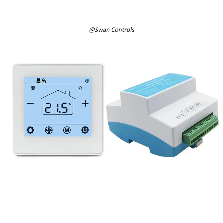
A digital thermostat should not be wired only by looking at terminal letters. Before wiring, installers and project buyers should confirm the system type, power supply, common wire, output signal, valve logic, fan control, sensor wiring, and communication requirements.
This article focuses on HVAC room control projects, especially fan coil units, heat pump systems, conventional heating and cooling systems, and electric heating applications. A digital thermostat here means a room control device for HVAC or heating projects, not an industrial temperature controller.
A digital room thermostat can work well only when the wiring matches the actual equipment. If the project uses the wrong voltage, wrong common wire, wrong reversing valve logic, wrong fan output, or wrong load rating, the screen may turn on but the system may still control incorrectly.
A buyer asks:
“The thermostat has many terminals. Can our installer just follow the labels?”
The safer answer is:
“Not yet. Terminal labels help, but they are not enough. Please confirm the system type and control logic first.”
Before wiring a digital thermostat, the goal is not to connect wires quickly. The goal is to avoid wrong control, system damage, installation delay, and customer complaints.
Confirm the System Type Before Wiring
Before wiring any digital thermostat, the installer should first confirm the actual application. Similar terminal labels do not always mean the same wiring sequence. A fan coil thermostat, heat pump thermostat, conventional HVAC thermostat, and electric heating thermostat all use different control logic.
Choosing the correct thermostat type first helps avoid wiring errors, commissioning delays, and customer complaints. Instead of starting with terminal letters, installers should always start with the controlled equipment.
Part One: Fan Coil Thermostat
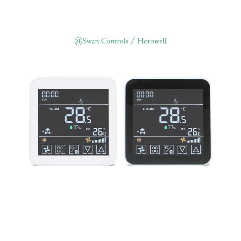
Fan coil applications are among the most common digital thermostat installations in commercial buildings, residential apartments, serviced residences, and hotel guest rooms. They are also one of the most frequently miswired thermostat applications in the field. The reason is simple: fan coil systems may look similar from the outside, but their internal control logic can vary significantly depending on the pipe arrangement, fan motor type, valve configuration, and building management requirements.
Before wiring any fan coil thermostat, installers should first identify the exact FCU configuration. A thermostat designed for a basic 2-pipe system cannot always be used directly on a 4-pipe system. Likewise, a thermostat intended for traditional three-speed AC fan motors will not properly control an EC fan requiring 0-10V modulation. Selecting the wrong thermostat often leads to valve malfunction, fan speed errors, poor room comfort, or complete commissioning failure.
A professional installation always begins with equipment verification, not terminal matching. Terminal labels such as L, N, LOW, MED, HIGH, and VALVE may appear straightforward, but wiring should only begin after the installer fully understands the actual operating sequence of the fan coil unit.
Why Correct FCU Identification Matters
Fan coil units are used in a wide variety of applications, including office buildings, hotels, hospitals, apartments, and retail spaces. Each project may have unique control requirements. Some systems require only local temperature control, while others must integrate with keycard switches, window contacts, occupancy sensors, or a central building management system.
Incorrect thermostat selection can create several common problems:
- The valve opens but the fan does not start.
- The fan runs continuously even after reaching setpoint.
- Cooling mode activates heating valves.
- EC fans fail to respond to relay outputs.
- BMS communication cannot be established.
- Hotel keycard energy-saving functions do not operate correctly.
Most of these issues originate from choosing the wrong thermostat model before installation even begins.
Key Checks Before Wiring an FCU Thermostat
- Is the system 2-pipe or 4-pipe?
- Does it use an on/off valve or a modulating valve?
- Is the fan a standard 3-speed AC fan or an EC fan?
- Does the project require automatic fan speed control?
- Is keycard input required for hotel applications?
- Does the building require RS485, Modbus, or BACnet integration?
- Are external room sensors, pipe sensors, or occupancy inputs needed?
These questions should always be answered before any wiring work starts. A few minutes of verification can prevent hours of troubleshooting later.
AC Fan vs EC Fan Control
Traditional FCUs commonly use three-speed AC fan motors. These are controlled by separate relay outputs for low, medium, and high speeds.
Modern energy-efficient buildings increasingly use EC fans. EC motors require analog 0-10V speed control rather than simple relay switching. Connecting relay outputs directly to an EC motor will not work and may damage the control electronics.
Always verify the fan motor type before selecting the thermostat.
Understanding 2-Pipe vs 4-Pipe Systems
A 2-pipe fan coil unit uses a single water coil that alternates between heating and cooling depending on the season. Only one valve output is typically required.
A 4-pipe system uses separate heating and cooling coils. This requires two independent valve outputs and a thermostat specifically designed for dual-valve control.
Installing a 2-pipe thermostat on a 4-pipe unit is one of the most common field mistakes. The result is incomplete temperature control and occupant complaints.
On/Off Valve vs Modulating Valve
An on/off valve operates in a simple open-or-close manner. When the thermostat calls for heating or cooling, the valve fully opens. Once the setpoint is reached, the valve fully closes. This control method is widely used in standard residential and commercial fan coil applications due to its simplicity and lower installation cost.
A modulating valve, by contrast, adjusts its opening continuously based on the room’s actual heating or cooling demand. Typically controlled by a 0-10V output, it provides more precise temperature regulation, improved comfort, and better energy efficiency.
Using an on/off thermostat with a modulating valve will prevent proper valve operation. Always verify the valve actuator type before selecting the thermostat.
BMS Communication Requirements
Many modern commercial buildings, hotels, and office projects require the fan coil thermostat to communicate with a Building Management System (BMS). This allows central monitoring, remote setpoint adjustment, scheduling, fault detection, and energy management.
Common communication protocols include RS485 Modbus, BACnet MS/TP, and, in some specialised projects, KNX or other proprietary protocols. The selected thermostat must support the exact protocol specified by the building automation system.
A non-communicating thermostat cannot simply be “upgraded” later through wiring changes alone. Communication capability must be built into the thermostat hardware from the beginning.
External Sensor Requirements
Some fan coil installations require additional sensors beyond the built-in room sensor. External room sensors are often used when the thermostat is mounted in an unsuitable location, such as near windows, return air grilles, or heat sources.
Pipe sensors can provide changeover control in 2-pipe systems by automatically detecting water temperature and switching between heating and cooling modes. Floor sensors, occupancy sensors, and window contacts may also be required in specialised applications.
Before wiring begins, always confirm whether external sensor inputs are required and whether the selected thermostat supports the necessary sensor type and resistance specification.
Common Wiring Mistakes
- Connecting a 2-pipe thermostat to a 4-pipe FCU.
- Using relay outputs for an EC fan that requires 0-10V control.
- Selecting the wrong valve output type.
- Ignoring keycard or BMS wiring requirements during installation.
- Failing to confirm fan voltage and relay capacity.
- Overlooking external sensor compatibility.
These errors often cause delayed commissioning, increased service calls, and avoidable replacement costs.
Recommended Thermostat Selection
For standard residential, office, and light commercial 2-pipe fan coil systems, HTW-WF08-FC-2 (← please click it directly) provides a reliable standalone solution with simple operation and easy installation.
For hotel projects requiring keycard integration, BACnet communication, and support for both 2-pipe and 4-pipe configurations,
HTW-WF11-FC-KB (← please click it directly)
is often the preferred option.
If the project uses EC fan motors or requires precise 0-10V modulating speed control,
HTW-WF11-FVM (← please click it directly)
is specifically designed for this application.
For advanced projects involving PICV control, remote sensors, or RS485 Modbus communication,
HTW-WF11-FC-MEN (← please click it directly)
offers greater integration flexibility.
The correct thermostat should always be selected based on the actual fan coil configuration, communication requirements, and end-user expectations.
When installers verify the system type first, fan coil thermostat wiring becomes far more predictable, commissioning is faster, and long-term system reliability improves significantly.
Part Two: Heating Thermostat
Heating thermostats are widely used in electric underfloor heating, hydronic floor heating, and boiler-based heating systems. Although the wiring may appear simple, heating applications require careful attention to load rating, sensor wiring, and control logic.
Before wiring a heating thermostat, the installer should confirm the heating type, supply voltage, heating load, sensor configuration, and whether the thermostat will switch the load directly or through a contactor.
A digital thermostat used for heating should always be selected according to the actual heating equipment and electrical load, not simply by appearance or display style.
Key Checks Before Wiring a Heating Thermostat
- Is the application electric heating, hydronic heating, or boiler control?
- What is the required supply voltage?
- Can the thermostat carry the heating load directly?
- Is a contactor required for higher current loads?
- Does the system use a floor sensor, room sensor, or both?
- What is the maximum floor temperature limit?
- Does the installation comply with local electrical regulations?
Common Wiring Mistakes
- Exceeding the thermostat’s rated current
- Using the wrong floor sensor type or resistance value
- Connecting high-power heating cables without a contactor
- Ignoring floor temperature protection settings
- Using the wrong supply voltage
For residential electric underfloor heating projects, HTW-WF02RP-16A3 (← please click it directly) is a practical solution when the system requires direct 16A load switching, floor sensor support, and smart Wi-Fi control.
Before installation, the heating cable power, supply voltage, and floor sensor compatibility should always be verified. Even the best digital thermostat cannot compensate for an overloaded circuit or incorrect sensor wiring.
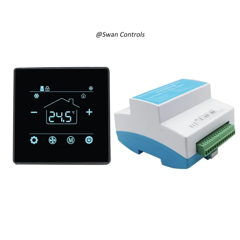
For larger electric heating loads, the thermostat may need to control an external contactor rather than switching the heating cable directly. This is especially important in commercial or large-area installations.

Part Three: Heat Pump Thermostat
Heat pump systems require more careful wiring than many other HVAC applications. A heat pump thermostat must control the compressor, reversing valve, auxiliary heat, emergency heat, and often multiple heating and cooling stages.
Before wiring a heat pump thermostat, the installer should confirm the system configuration, compressor stages, reversing valve logic, auxiliary heating type, and power supply. Terminal labels alone are never enough.
A digital thermostat designed for conventional HVAC cannot automatically be used for heat pump systems. Heat pump control sequences are different and must match the equipment exactly.
Key Checks Before Wiring a Heat Pump Thermostat
- Is it a single-stage or multi-stage heat pump?
- Does the system require AUX heat or emergency heat?
- Is the reversing valve energised in cooling or heating?
- What are the required compressor stages?
- Are R and C wires available for stable 24V power?
- Is the backup heat electric, gas, or another source?
- Does the project require Wi-Fi or remote access?
Common Wiring Mistakes
- Incorrect O/B reversing valve setting
- Miswiring AUX and emergency heat outputs
- Using a conventional thermostat on a heat pump system
- Ignoring multi-stage compressor requirements
- Missing the common wire for Wi-Fi operation
A very common field problem occurs when the room heats while cooling is selected. In most cases, the reversing valve logic is configured incorrectly rather than the equipment being faulty.
For residential and commercial heat pump projects,
HTW-MT8600 (← please click it directly)
supports conventional HVAC systems, heat pump systems with or without AUX, reversing valve control, and multi-stage operation up to 2-stage cooling and 3-stage heating.
Before applying power, installers should always verify O/B logic, AUX heat type, compressor staging, and thermostat configuration settings. Correct setup is just as important as correct wiring.
Part Four: Conventional HVAC Thermostat
Conventional HVAC systems remain one of the most widely installed thermostat applications worldwide. These systems typically control separate heating and cooling equipment, making correct terminal identification essential before wiring begins.
Before wiring a conventional thermostat, installers should confirm the number of heating and cooling stages, equipment type, transformer voltage, and whether additional accessories such as humidifiers or ventilation controls are required.
A digital thermostat for conventional systems must match both the equipment staging and the control voltage. Using an incompatible thermostat can lead to poor system performance or complete operational failure.
Key Checks Before Wiring a Conventional HVAC Thermostat
- Is the system single-stage or multi-stage?
- What type of heating equipment is installed?
- Is the control voltage standard 24VAC?
- Are separate heating and cooling transformers used?
- Is a common wire available for smart thermostat operation?
- Are accessories such as humidifiers, dehumidifiers, or ventilation controls required?
- Does the project require Wi-Fi, app control, or BMS integration?
Common Wiring Mistakes
- Confusing conventional HVAC wiring with heat pump wiring
- Incorrectly connecting Y, W, and G terminals
- Omitting the common wire for smart thermostat models
- Ignoring multi-stage configuration settings
- Failing to isolate dual-transformer systems properly
For standard residential and light commercial applications,
HTW-MT8600 (← please click it directly)
is a versatile solution that supports both conventional HVAC and heat pump systems, including multi-stage heating and cooling configurations.
A conventional thermostat should never be selected based solely on appearance. Always verify staging compatibility, voltage requirements, and accessory control needs before installation.
Correct thermostat configuration after wiring is equally important. Even perfectly connected terminals can cause operational problems if the installer selects the wrong system mode during setup.

Practical Case 1: Heat Pump Wiring with Reversing Valve
A project uses a heat pump system with AUX heat. The installer connects the power and compressor terminals correctly, but the room heats when cooling is requested.
The issue may be O/B reversing valve logic. Some systems energise the reversing valve in cooling, while others energise it in heating. If the setting is wrong, the system responds opposite to the user’s request.
In this case, the installer should confirm the heat pump equipment sequence, O/B logic, AUX heat type, and stage outputs before wiring. HTW-MT8600 is suitable for this type of project because it supports heat pump systems, reversing valve control, AUX heat, and multi-stage operation.
Practical Case 2: Hotel FCU with Keycard and BMS
A hotel room uses a fan coil unit, keycard input, and BACnet connection. The thermostat powers on, but the BMS cannot read all values, and the room does not follow the expected energy-saving logic.
The issue may not be the display. The project team may not have confirmed BACnet object points, keycard logic, or 2/4-pipe wiring before installation.
For this type of hotel FCU project, the buyer should confirm wiring diagrams, object lists, and room control sequence before bulk order. HTW-WF11-FC-KB is more suitable than a simple standalone thermostat when keycard and BMS control are required.
Practical Case 3: Electric Floor Heating Load
A residential electric heating project focuses on Wi-Fi control and display design first. After installation, the customer complains about unstable heating.
The installer later finds that load rating and floor sensor logic were not fully checked before wiring.
For electric heating, the correct process is to confirm supply voltage, heating cable power, rated current, floor sensor wiring, and safety requirements first. App control is useful, but it cannot solve a load or sensor mismatch.
For 16A electric underfloor heating projects, HTW-HT09-16A3 can be used when the wiring and load match the requirement.
FAQ
What should be confirmed before wiring a digital thermostat?
Before wiring a digital thermostat, confirm the system type, power supply, common wire, fan type, valve output, sensor wiring, load rating, and communication requirement. The wiring diagram should be checked against the real HVAC or heating equipment.
Why is the common wire important for a 24V thermostat?
The common wire provides the return side of the 24V power circuit. Many Wi-Fi and smart HVAC thermostats need stable R and C power. If the common wire is missing or wrong, the thermostat may not power on reliably.
What should be checked before wiring a heat pump thermostat?
Before wiring a heat pump thermostat, check R/C power, compressor stages, O/B reversing valve logic, AUX heat, emergency heat, and fan output. Wrong O/B setting can make the system heat when cooling is requested.
Can a digital room thermostat be used for both FCU and heat pump systems?
Only if the model is designed to support both applications. FCU systems usually need fan and valve control, while heat pump systems need compressor, reversing valve, AUX heat, and stage control. Always confirm the model before wiring.
Why should Modbus or BACnet points be confirmed before wiring?
Modbus or BACnet points should be confirmed before wiring because BMS integration depends on the correct address, baud rate, register list, object list, and read/write points. Without these details, the system may power on but fail during commissioning.
Final Note / Practical Takeaway
Digital thermostat installation should start before wiring tools are used.
The installer should first confirm the system type, power supply, output logic, fan type, valve type, heat pump stages, reversing valve logic, sensor wiring, load rating, and communication requirements. Terminal labels are useful, but they are not a replacement for system confirmation.
A digital room thermostat should make installation easier and room control more stable. If buyers and installers confirm the wiring logic before power is applied, they can reduce wrong control, product damage, commissioning delays, and customer complaints.
For heat pump and conventional HVAC projects, HTW-MT8600 is useful where 24V power, reversing valve, AUX heat, and multi-stage control must be confirmed carefully. For FCU and heating projects, the correct model should still be selected based on fan type, valve output, communication need, and load rating.
References / Sources
- U.S. Department of Energy, “Programmable Thermostats.” https://www.energy.gov/energysaver/programmable-thermostats
- U.S. Department of Energy, “Air-Source Heat Pumps.” https://www.energy.gov/energysaver/air-source-heat-pumps
- ENERGY STAR, “Smart Thermostats.” https://www.energystar.gov/products/smart_thermostats
- ENERGY STAR, “Air Source Heat Pumps.” https://www.energystar.gov/products/air_source_heat_pumps
- ASHRAE, “BACnet™, the ASHRAE Building Automation and Control Networking Protocol.” https://www.ashrae.org/technical-resources/bookstore/bacnet
- BACnet International, “About the BACnet Standard.” https://bacnet.org/about-bacnet-standard/
- Modbus Organization, “Modbus Organization.” https://www.modbus.org/
- ASHRAE, “Standard 55: Thermal Environmental Conditions for Human Occupancy.” https://www.ashrae.org/technical-resources/bookstore/standard-55-thermal-environmental-conditions-for-human-occupancy
- International Energy Agency, “Space Cooling.” https://www.iea.org/energy-system/buildings/space-cooling
- U.S. Energy Information Administration, “Use of Energy Explained: Energy Use in Homes.” https://www.eia.gov/energyexplained/use-of-energy/homes.php