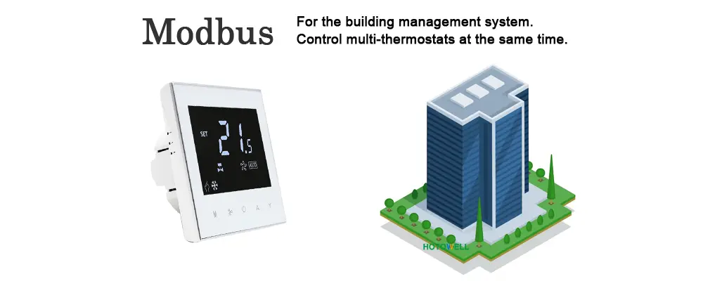
“Why is the Modbus thermostat online, but the BMS still cannot use it properly?”
“Because compatibility problems usually come from more than one layer. Protocol settings, RS485 wiring, addressing, register mapping, and the actual FCU control logic all need to match.”
That is the real reason many Modbus thermostat projects feel more difficult than expected. On paper, everything looks correct. The thermostat says Modbus. The gateway says Modbus. The BMS team says the project uses Modbus RTU over RS485. But once the project starts, the room thermostat may still fail to behave correctly. The device may appear online yet not respond as expected. Some registers may read, but fan speed may not change. Setpoint values may be visible, but the FCU still does not run in the right way. In these situations, buyers often blame the thermostat first. In reality, the problem usually starts with matching, not with the word Modbus itself.
This is why compatibility should be treated as a multi-layer project question, not a simple product label. A Modbus thermostat can be fully legitimate and still be wrong for a project if the serial parameters do not match, if two devices share one address, if the BMS uses the wrong register list, or if the thermostat’s FCU control logic does not match the real fan coil system. The Modbus protocol specification defines the communication framework, but practical compatibility still depends on correct implementation choices across the whole system. That is exactly what this article explains. It focuses on the most common compatibility issues in real HVAC thermostat projects and shows how buyers, integrators, and OEM customers can avoid them before the site team starts chasing “communication problems.”
Quick Summary: The 5 Compatibility Checks That Solve Most Problems
The fastest way to reduce Modbus thermostat compatibility problems is to check five things in order. First, confirm the RS485 physical layer and basic wiring structure. Second, confirm that baud rate, parity, stop bits, and related serial parameters are identical across devices. Third, confirm that each thermostat uses a unique Modbus address. Fourth, confirm that the BMS or gateway uses the correct register list and function expectations. Fifth, confirm that the thermostat’s FCU control type matches the real application, such as 2-pipe, 4-pipe, 3-speed fan, EC fan, 2-point valve control, or 0–10V modulation. Most “Modbus problems” become much easier once these five checks are made systematically.
What “Compatibility” Really Means in a Modbus Thermostat Project
In HVAC projects, compatibility is often misunderstood as “the devices all say Modbus, so they should work together.” That is too simple. Modbus compatibility in a real thermostat project means the thermostat, the physical communication layer, the serial settings, the control system, and the application logic all align with one another. If one layer is wrong, the project may partially work or appear online, but still fail in practical use.
The Modbus Application Protocol Specification defines Modbus as an application-layer messaging protocol at OSI level 7 for client/server communication between devices on different buses or networks. That definition is important because it shows what Modbus does and what it does not do. It defines a communication framework. It does not automatically guarantee that every device will use the same address plan, the same register layout, or the same FCU control meaning. Compatibility therefore must be checked beyond the protocol name.
For thermostat buyers, this means one practical thing: a Modbus thermostat project should always be reviewed at both communication level and control-application level. If either one is ignored, site problems become much more likely.
Issue 1: RS485 and Modbus Are Not the Same Thing
This is one of the most common sources of confusion. Buyers often ask for an RS485 thermostat when they really mean a Modbus RTU thermostat over RS485. Others ask for a Modbus thermostat and assume the physical layer has already been defined. These are related questions, but they are not the same question.
Modbus is the communication protocol. RS485 is a commonly used serial physical layer. The Modbus over Serial Line guide identifies TIA/EIA-485 two-wire as the most common physical interface for Modbus over serial line. In practice, this means a project can have the correct physical wiring standard but still fail at protocol settings, and it can also have the correct protocol expectations while still being wired badly at the physical layer.
| Term | What It Is | Why Confusion Causes Problems |
|---|---|---|
| Modbus | Communication protocol | People may assume all Modbus devices are automatically interoperable |
| RS485 | Physical serial interface | Wiring may be correct physically while protocol settings are still wrong |
| Modbus RTU | Common serial Modbus implementation | Most HVAC thermostat projects actually mean this specific combination |
So the first practical rule is simple: always separate the physical layer question from the protocol question. Do not treat “RS485” and “Modbus” as interchangeable shortcuts in project documentation.

Issue 2: Address Conflicts and Node Planning
Address conflicts are a very common compatibility issue because they are easy to create and easy to miss. A standard Modbus network can usually address up to 247 server devices, and each server should have a unique address between 1 and 247. If two thermostats use the same server address, the network may behave unpredictably, one device may overwrite another logically, or the BMS may not distinguish them correctly. Schneider Electric’s guidance on Modbus addressing reflects this standard project requirement clearly. :contentReference[oaicite:3]{index=3}
This problem appears most often in multi-room hotel, office, or FCU projects where many room thermostats are deployed together. During sample testing, one thermostat may work perfectly on its own. During building deployment, repeated default addressing can create communication confusion across multiple rooms. The buyer then concludes that the Modbus thermostat is “unstable” when the real issue is node planning.
The easiest way to prevent this is to prepare an address plan before installation and commissioning. Do not wait until the thermostats are already mounted in dozens of rooms. Good address discipline is one of the cheapest ways to prevent expensive troubleshooting later.
Issue 3: Baud Rate, Parity, Stop Bits, and Serial Settings Mismatch
This is the classic “everything looks right but nothing works” problem. A thermostat can be correctly wired on RS485 and still fail completely if baud rate, parity, stop bits, or related serial parameters do not match the gateway or BMS configuration. Modbus serial communication is not only about physical connection. It depends on communication settings being aligned across the network. The serial line specification makes clear that Modbus over serial line is a structured implementation, which means communication timing and framing assumptions must still be consistent between devices.
This kind of mismatch is especially frustrating because the thermostat can appear fine as a local room thermostat while refusing to communicate correctly at system level. Installers often lose time here because the device is powered, the screen works, and the cable is connected. That visual reassurance makes the serial-parameter mismatch harder to spot.
For buyers and project managers, the best way to avoid this issue is to demand a written communication parameter sheet before integration testing begins. Do not assume the defaults are universal. Confirm them explicitly.
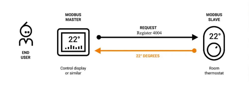
Issue 4: Register Map Mismatch
This is often the most expensive compatibility issue because it wastes time even after the devices appear to communicate. The thermostat may be online. The BMS may read values. But if the register addresses, function-code expectations, or data interpretation are wrong, the project still fails in practice.
The Modbus protocol defines function-code-driven access to data such as coils, discrete inputs, input registers, and holding registers. That framework is standard, but the application-level meaning of the registers in a thermostat still depends on the manufacturer’s implementation. A building system can therefore be “connected” and still be functionally wrong if it reads the wrong holding register for setpoint, maps fan speed incorrectly, or assumes a valve output meaning that does not match the actual thermostat logic. :contentReference[oaicite:5]{index=5}
This is why register mapping should be treated as a compatibility document, not as optional technical detail. If the project does not have a verified register list, then the thermostat is not yet truly compatible with the system, even if the wiring and serial settings are correct.
Issue 5: FCU Control Logic Does Not Match the Thermostat
This is the most important application-level compatibility problem for your product range because many “Modbus thermostat issues” are not really Modbus issues at all. They are FCU control mismatches that happen to appear inside a Modbus project.
2-pipe vs 4-pipe mismatch
If the thermostat is intended for 2-pipe FCU logic but the project uses 4-pipe control, or the reverse, the building team may see wrong heating/cooling behaviour and conclude there is a communication problem. In reality, the thermostat was simply matched to the wrong FCU control structure.
2-point vs 0–10V output mismatch
Advanced projects using 0–10V modulation or related control strategies need thermostats whose outputs actually support that logic. A project using standard 2-point on/off control should not automatically be matched to a 0–10V-centered thermostat just because the feature list looks richer.
3-speed fan vs EC fan mismatch
Fan control type also matters. If the thermostat is chosen with a different fan-control expectation from the real FCU design, the result may again look like a communication issue while the real problem is control compatibility.
This is exactly why product selection should begin with the real control type. A model such as the indoor Modbus thermostat for 2-pipe fan coil unit system, the popular Modbus thermostat for 4-pipe fan coil unit systems, the FCU 3 fan speed 0–10V modulating thermostat with Modbus, the 24VDC output PICV thermostat with Modbus keycard energy saving, or the durable indoor BMS smart Modbus thermostat for 4-pipe FCU system should be judged first by FCU logic fit, then by protocol. Matching the wrong control family is one of the fastest ways to create expensive “compatibility” complaints later.
Issue 6: Wiring, Shielding, and Common Line Problems
Physical layer discipline matters more than many buyers expect. The Modbus serial-line legacy guide states that serial line systems should use shielded cable, and that RS485 Modbus systems typically use the balanced pair D0 and D1 together with a common reference. It also warns that incorrect crossed wiring can be damaging. These are not cosmetic details. They directly affect whether the bus behaves reliably.
In real FCU projects, poor shielding, missing common reference practice, or loose wiring discipline often shows up as intermittent communication rather than total failure. That makes the issue harder to diagnose because the thermostat may appear to work sometimes and fail at other times. Long cable runs, electrically noisy environments, or poor installation quality can all increase the risk.
This is why compatibility should never be treated as only a software or BMS-side problem. In RS485-based thermostat networks, wiring quality is part of compatibility.
Issue 7: Gateway or BMS Integration Assumptions
Some projects assume that if the thermostat is Modbus and the BMS accepts Modbus, the gateway layer will take care of everything automatically. That assumption causes trouble. The Modbus Messaging Implementation Guide explains how Modbus can operate across different network structures through gateways and client/server models. That is useful, but it also means the gateway layer becomes another place where assumptions can go wrong.
The thermostat may be correct. The serial bus may be correct. But if the gateway expects a different register structure, a different polling strategy, or a different mapping logic into the supervisory system, the project may still fail functionally. This is why compatibility in a real building project is often a three-party issue: thermostat, gateway, and BMS.
Buyers who treat gateway configuration as a later detail often discover this too late. It is better to define the integration path in advance.
How to Avoid These Compatibility Issues Before Ordering
The cheapest time to solve compatibility is before the order is placed. Once devices are on the wall and multiple teams are involved, even simple mismatches become expensive.
- Confirm the FCU type clearly: 2-pipe, 4-pipe, 3-speed, EC fan, 2-point valve, 0–10V, or PICV-related control.
- Confirm whether the project is Modbus RTU over RS485, Modbus/TCP through gateway, or another integration structure.
- Request the complete serial communication parameter list in writing.
- Prepare a unique address plan before commissioning.
- Obtain the register list and check how the BMS intends to use it.
- Review wiring, shielding, and common-reference practice before site installation begins.
These steps are not complicated, but they prevent most avoidable compatibility problems. They also help buyers compare suppliers more intelligently, because a supplier who can support these checks usually reduces project risk more effectively than one who only says “our thermostat supports Modbus.”
Expert Commentary: Most “Modbus Problems” Are Really Matching Problems
This is the most important conclusion in the article. Most compatibility complaints do not start with a broken thermostat. They start with a wrong assumption. Someone assumes that RS485 and Modbus mean the same thing. Someone assumes the default serial settings match automatically. Someone assumes the register list will be obvious. Someone assumes a 4-pipe thermostat can be dropped into a 2-pipe control design. Someone assumes “online” means “fully compatible.”
In practice, compatibility is achieved through matching, not through naming. A thermostat that is perfectly compatible on the protocol level can still be a poor project fit if the FCU logic, output structure, or register usage are wrong. Buyers who understand this early usually save much more time than buyers who begin troubleshooting only after site commissioning goes wrong.
Industry Trend: Why Compatibility Matters More as HVAC Systems Become More Integrated
Compatibility matters more today because HVAC systems are more integrated than before. The Modbus Organization continues to publish and maintain protocol, serial line, TCP/IP messaging, and security specifications. That continuing ecosystem support reflects the fact that Modbus is still actively used where interoperability and structured communication are needed. As buildings rely more on centralized control, gateway layers, and system-level visibility, thermostat compatibility becomes more important, not less. :contentReference[oaicite:8]{index=8}
This does not mean every thermostat project should become more complex. It means that projects using Modbus should become more disciplined about how they define compatibility. The cost of vague assumptions rises as the integration level rises.
Scientific Data and What It Means
Several technical facts from the official documents help explain why compatibility failures happen. Modbus is defined as an application-layer protocol at OSI level 7. RS485 two-wire is identified as the most common physical interface for Modbus over serial line. Standard Modbus networks use unique server addresses, typically from 1 to 247. The serial-line legacy guidance also emphasizes shielded cable and balanced-pair wiring with common reference in RS485 implementations. These are not abstract technical details. They are the practical layers that determine whether a thermostat can be integrated successfully into a real FCU and BMS project.
Real Cases and User Feedback
Case 1: A 2-pipe project where 4-pipe logic caused confusion
One buyer initially focused on the protocol label and selected a thermostat from a richer product group without clarifying the FCU application carefully enough. The project later behaved in a way that looked like a communication issue, but the real problem was that the FCU control logic did not match the thermostat family as cleanly as expected.
Case 2: A BMS project where addressing and register planning solved the issue
Another project had thermostats online but still experienced functional problems at system level. Once the team reviewed device addresses and the exact register expectations used by the supervisory system, the “compatibility problem” became much more concrete and much easier to solve.
Case 3: A 0–10V / PICV project where output mismatch looked like protocol failure
In a third case, the thermostat communicated, but the field behaviour still did not match project expectations. The cause was not the Modbus stack. The cause was a mismatch between expected output logic and actual FCU/PICV control structure.
User feedback pattern: Buyers rarely regret checking compatibility layers too early. They usually regret assuming the project was compatible just because the product page and the BMS both contained the word Modbus.
Frequently Asked Questions
1. Why is my Modbus thermostat online but not communicating correctly?
Because being online does not guarantee full compatibility. The project may still have mismatched serial settings, duplicate addresses, wrong register mapping, gateway assumptions, or FCU control logic that does not match the thermostat.
2. What is the difference between RS485 and Modbus in a thermostat project?
RS485 is commonly the physical serial communication layer, while Modbus is the communication protocol. In many HVAC projects, a Modbus RTU thermostat uses RS485 as the transport path.
3. What causes Modbus thermostat compatibility problems most often?
The most common causes are serial parameter mismatches, address conflicts, wrong register mapping, poor RS485 wiring practice, and FCU control logic that does not match the thermostat model.
4. Can a 2-pipe and 4-pipe Modbus thermostat be used interchangeably?
Not safely as a general rule. A 2-pipe and 4-pipe FCU project use different control logic, so the thermostat should be matched to the actual application rather than treated as interchangeable just because both support Modbus.
5. How can I avoid Modbus thermostat compatibility issues before ordering?
You should confirm the FCU type, output logic, serial settings, device address plan, register list, and gateway or BMS integration path before placing the order.
References / Sources
- Modbus Organization, Modbus Application Protocol Specification V1.1b3
- Modbus Organization, Modbus Serial Line Protocol and Implementation Guide V1.02
- Modbus Organization, Modbus Over Serial Line for Legacy Applications Only
- Modbus Organization, Modbus Messaging on TCP/IP Implementation Guide V1.0b
- Modbus Organization, Specifications and Implementation Guides
- Modbus Organization, Introduction to Modbus
- Schneider Electric, How many Devices can be connected in Modbus network?
- Schneider Electric, SpaceLogic Thermostat – TH900 Series Thermostat – Installation Instructions
- Sauter, Modbus fan coil thermostat datasheet
- Wikipedia, Modbus