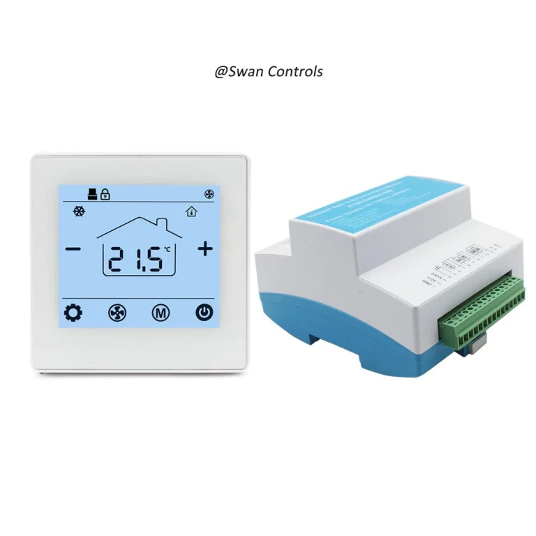
“Can this thermostat work with our project?”
“Maybe. But first we need to confirm what it needs to sense, what it needs to switch, and what kind of output the system really accepts.”
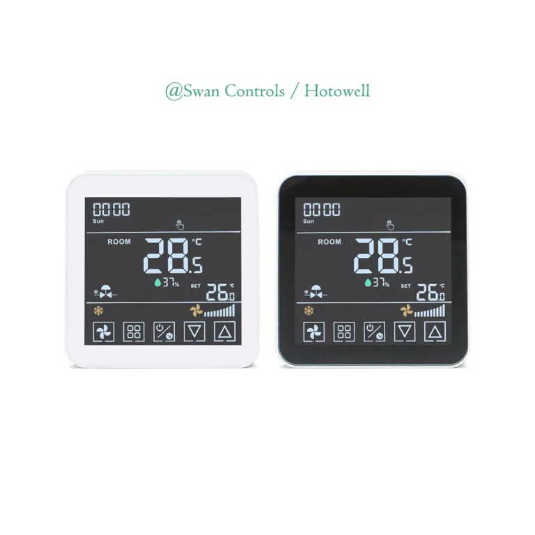
That is where many thermostat mistakes begin. The screen looks right. The voltage looks close enough. The wall plate seems standard. But the project still fails after installation. Sometimes the room temperature reading is wrong. Sometimes the valve does not move. Sometimes the fan runs at the wrong time. Sometimes the boiler receives the wrong signal. In other cases, the thermostat is installed neatly, but the hotel keycard logic, changeover logic, or PICV control still does not work.
The problem is often not the thermostat quality itself. The problem is that the thermostat was not matched correctly with the sensor type, relay logic, or output type. Honeywell and Resideo installation material makes this point very clearly: thermostat compatibility depends on more than appearance, and different products may or may not support remote sensors, relay terminals, or certain applications.
Quick Summary
To match a thermostat correctly, buyers should confirm three things first: what temperature or status the thermostat needs to sense, what device it needs to switch or control, and what output logic the target system actually accepts. If any one of these is wrong, the thermostat may still install neatly but still control the system incorrectly.
Quick Summary: The 3 Matching Questions That Prevent Most Thermostat Control Errors
The fastest way to avoid most thermostat control problems is to ask three questions before selection or wiring. First, what sensor does the thermostat need: built-in room sensing, remote room sensing, pipe sensing, or another special input? Second, what relay logic does the controlled device need: dry contact, heat relay, fan relay, or a specific relay state? Third, what output type does the system actually accept: simple on/off, relay switching, 24VDC valve output, or communication-based integration? If these three answers are clear, the thermostat selection becomes much easier. If they are unclear, the project often moves into trial-and-error mode.

Why Thermostat Matching Is More Than a Wiring Task
Many buyers treat thermostat matching like a late-stage wiring issue. In reality, it should be treated as an early-stage control decision. A thermostat is not only a wall interface. It is a control node that connects sensing, logic, and output. If any of those three elements do not match the real HVAC application, the project may show the wrong temperature, switch the wrong circuit, or send the wrong command to the target device.
This is why thermostat problems are often misunderstood. A site team may say the thermostat is not accurate, but the real issue may be that the thermostat is using the wrong sensor location. Another project may say the thermostat does not control the fan correctly, while the actual problem is that the equipment expected independent fan relay logic and the selected thermostat did not provide it. A third project may say the thermostat cannot control the valve, but the real mismatch may be that the valve requires a 24VDC output or a specific control method rather than a simple dry contact.
In other words, thermostat matching is really about control architecture. Wiring only becomes straightforward after the sensing method, relay logic, and output type have already been confirmed.
Start by Matching the Sensor Type
The first matching task is sensing. A thermostat can only make correct control decisions if it is sensing the right condition in the right place.
Built-in room sensor
A built-in room sensor is the simplest option and works well in many standard room thermostat applications. If the thermostat is mounted in a representative location, the built-in sensor can provide stable control without extra field wiring. This is often suitable for basic residential rooms or simple local control applications.
But this simplicity has a limit. If the thermostat is installed near sunlight, drafts, warm equipment, a door, or a badly ventilated wall area, the sensor may read a local temperature that does not represent the occupied zone. At that point, the thermostat may still operate correctly according to its own reading, but the actual room comfort will feel wrong.
Remote room sensor
A remote room sensor is often the better choice when the thermostat location is not the best sensing location, or when the thermostat must be installed where users can access it but where temperature conditions are not representative. This is especially useful in projects where the thermostat is placed near entrances, corridors, decorative walls, or hotel room control points.
This is not a minor feature. Resideo’s TB7220 documentation states that if a remote indoor temperature sensor is connected, the thermostat displays the indoor temperature from the remote sensor, and the thermostat’s internal sensor is not used. That is a very important matching rule. It means a remote sensor is not simply an added reference. In some products, it becomes the main sensing source.
For buyers, the lesson is simple. Do not ask only whether a thermostat supports a sensor. Ask what happens to the internal sensor when that sensor is connected.
Pipe sensor or changeover sensor
Pipe sensing or changeover sensing is especially important in hydronic, fan coil, and 2-pipe applications. In those systems, the thermostat may need to understand more than room temperature. It may also need information about whether the system is currently in heating or cooling mode, or whether a pipe temperature indicates a seasonal or operational change.
Resideo’s MultiPRO multispeed and multipurpose thermostat documentation is useful here because its wiring examples explicitly include indoor temperature sensor, remote setback/changeover, and pipe sensor inputs in the same control family. It also shows two-pipe heat/cool relay logic and multiple fan relays. That is exactly the kind of structure that shows why matching matters. In these systems, the thermostat is not simply reading room air and toggling one output. It may be working inside a wider set of field signals.
Special sensors and unsupported sensor inputs
Another common mistake is to assume every thermostat supports extra sensor inputs. That is not true. Honeywell’s X2S smart thermostat compatibility page states that the model does not support input on S terminals for indoor and outdoor sensors. In the same list, it also says the product does not support relay U terminals. That kind of limitation is exactly why buyers should confirm supported inputs before they order.
A thermostat that looks modern and connected may still be the wrong product if the project needs external sensing or special field inputs.
| Sensor Type | Best For | Main Risk if Mismatched |
|---|---|---|
| Built-in room sensor | Standard room thermostat use | Wrong reading if location is poor |
| Remote room sensor | Better sensing position or concealed-unit control | Internal sensor logic may be bypassed |
| Pipe sensor | 2-pipe and hydronic changeover logic | Wrong seasonal or mode decision |
| Special or floor sensor | Surface protection or special zone control | Unsupported input or wrong response |
Then Match the Relay Logic
Once the sensing method is clear, the next task is switching logic. This is where many field errors happen because buyers often use general phrases like supports heating or supports fan without asking what that really means electrically.
Heat relay and fan relay are not the same thing
Relay matching starts by identifying what the thermostat is actually switching. Resideo’s TB7220 wiring examples clearly show separate heat relay, cool relay, and fan relay functions. That distinction matters because the controlled device may expect different switching behaviour for heating demand, cooling demand, or fan operation. A thermostat that supports one of these may not automatically support all of them in the way the field device requires.
Independent fan control needs to be confirmed
Honeywell’s FocusPRO wiring diagrams add another useful reminder. In the heat-only furnace wiring note, Honeywell states that G is used for independent fan control only, and that most heat-only gas or oil forced-air systems do not use a G wire. That single note explains why fan logic should never be assumed. Some applications expect separate fan switching. Others do not. A buyer who sees a thermostat with a fan icon should still confirm whether the project actually needs independent fan relay behaviour.
Relay state and application suitability
Some commercial thermostats also require installers to check the product ratings and application suitability before installation. Resideo’s TB8220 commercial thermostat document says installers should check the ratings given in the instructions and on the product to ensure the product is suitable for the application. This is basic advice, but it is very important. Relay matching is not just about whether a terminal exists. It is also about whether the thermostat is intended for that control load and logic.
Dry contact versus powered relay
In buyer language, many people say relay output when they really mean any switching output. That is not precise enough. Some systems need a dry contact. Others need a powered relay path. Others require staged relays or fan-speed relays. The field device does not care what the thermostat marketing calls it. It only responds to the actual switching logic presented at its terminals.
This is why relay matching should always begin from the controlled equipment side. Ask what the boiler, valve, fan board, or field controller expects. Then match the thermostat accordingly.

Finally Match the Output Type
This is where many projects become much easier or much harder. Output type should not be treated as a small technical detail. It should be treated as a selection filter.
Simple on/off or dry contact output
For many boiler and basic heating applications, simple on/off or dry contact logic is enough. In these cases, the thermostat is mainly acting as a demand switch. If the project needs straightforward call-for-heat logic, this type of output is often the most practical.
That is why boiler-related products such as a 220V boiler thermostat with Modbus or a house thermostat for water heating and boiler heating can be easier for buyers to evaluate. They already point toward a defined control context rather than a generic wall control assumption.
Relay output for water heating or fan switching
Water heating and similar applications often need stable switching rather than complex integration. In these systems, the output may still be simple, but the matching still matters. The thermostat must match the voltage, the switching requirement, and the overall control role in the system. A product such as a 3A water heating thermostat makes more sense when the buyer is evaluating relay-based heating control rather than trying to stretch a generic room thermostat into a role it was not designed for.
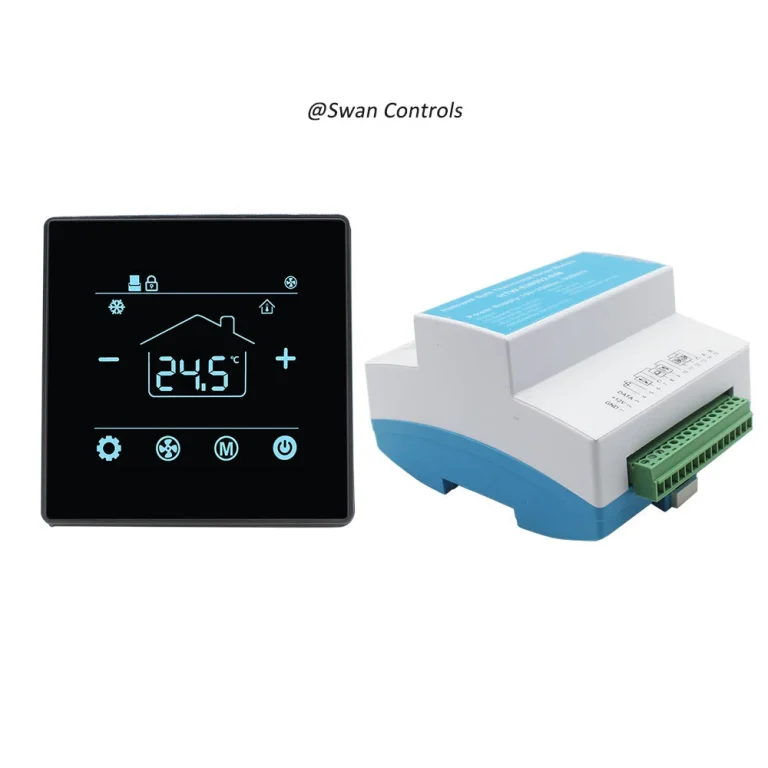
24VDC output for PICV or valve control
This is one of the most important distinctions in commercial room control. If a project uses PICV logic or a valve actuator expecting a certain control method, a simple relay thermostat may not be enough. The thermostat may need 24VDC output or another specific control form.
This is exactly why a 24VDC output PICV thermostat with Modbus exists as a distinct product direction. The key point is not that it is more advanced. The key point is that it is matched to the target control method.
Hotel thermostat outputs with keycard or setback logic
Hotel projects are also a strong example of output matching. A normal room thermostat may appear to work, but if the project needs keycard-linked setback, occupancy logic, or specific hotel control response, the output behaviour and logic path must support that role. A dedicated keycard HVAC thermostat is usually a better fit when the thermostat is part of a hospitality control workflow rather than only a local room temperature device.
Communication output is not the same as control output
Another major mistake is to confuse communication features with control outputs. WiFi, Modbus, and app connectivity are not the same as heat relays, dry contacts, or 24VDC outputs. A thermostat may communicate perfectly and still be wrong for the target load. Communication should be evaluated separately from switching or control output.
Different HVAC Applications Need Different Matching Rules
This title becomes much easier when buyers stop asking Which thermostat is best and start asking Which thermostat logic fits this HVAC application.
Boiler heating
For boiler projects, buyers should usually start by confirming whether the system wants a simple heating demand, a specific power requirement, or additional communication support. Sensor matching is often simpler here, but output and relay matching still matter.
Water heating
Water heating projects usually benefit from stable sensing and practical relay logic. The thermostat should be selected for the actual heating control method rather than for appearance or general thermostat marketing.
PICV or valve control
For PICV and commercial valve control, the output type often becomes the deciding factor. A thermostat without the correct output logic may still look suitable on paper and still fail in the field.
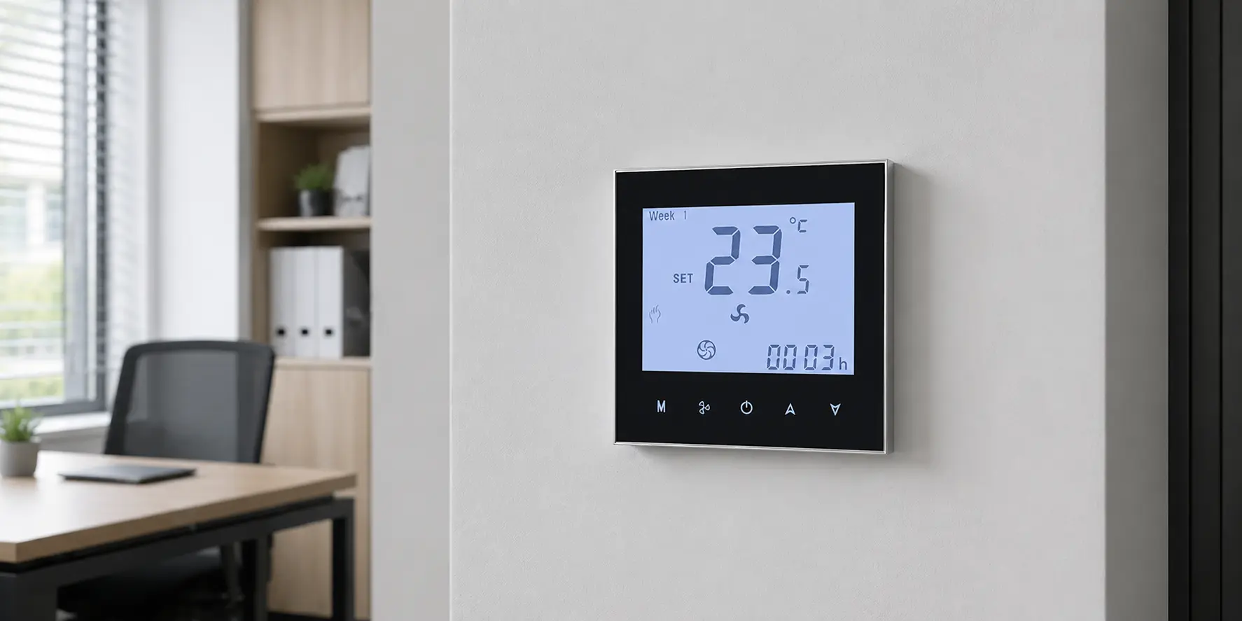
Office room HVAC
Office applications often combine room sensing, and specific control behaviour. That means sensor matching, relay logic, and output matching all matter at the same time.
Common Matching Mistakes Buyers Should Avoid
- Choosing by screen style instead of by sensor and output logic.
- Assuming every room thermostat supports remote sensors.
- Confusing Modbus or WiFi with actual load control.
- Ignoring fan relay requirements.
- Selecting a simple relay thermostat for a PICV application.
- Using a generic room thermostat in a hotel project that actually needs keycard setback logic.
- Assuming all low-voltage thermostats share the same terminal meanings.
- Ignoring unsupported sensor inputs or unsupported relay terminals.
Honeywell documentation even warns that some models require 24 VAC C wire, do not support sensor inputs on S terminals, and do not support relay U terminals. So even within a similar category, input and output support can vary significantly.
Expert Commentary & Analysis
A useful way to think about thermostat troubleshooting is this: many field complaints are not caused by product failure first. They are caused by mismatching first. Installers and buyers often begin by asking whether the thermostat is faulty. In many cases, the more useful first question is whether the thermostat was correctly matched to the application, sensor logic, relay requirement, and output type.
Resideo’s commercial installation documentation supports this mindset. Its TB8220 guidance tells installers to check product ratings and suitability for the application before installation. That is a strong reminder that thermostat selection is part of control design, not just part of product sourcing.
At the same time, DOE documents show that thermostats and related control packages are becoming more capable sensing and diagnostic devices. In a DOE school RTU replacement package, replacement thermostats are described as including zone-level carbon dioxide sensors and advanced economizer diagnostics. That means the market is moving beyond simple wall-mounted temperature control and toward broader sensing and control roles. In that kind of environment, matching logic matters even more than before.
Scientific Data and Industry Direction
The thermostat market is changing. It is no longer only about local temperature display and a basic relay. DOE’s school RTU replacement guidance describes thermostat packages that include zone-level CO2 monitoring and advanced diagnostics. That is a strong sign that modern thermostats are increasingly integrated into wider sensing and control systems.
ASHRAE also reports on smart thermostat research that used temperature and occupancy data from each zone in a single-family residence and analyzed measured indoor environmental conditions and electricity savings. That kind of work shows that sensing quality and control logic are now being evaluated together, not as separate topics. In other words, the sensor side and the control side are both becoming more important in real-world thermostat performance.
For buyers, this means thermostat matching is becoming more technical, not less. As products take on more sensing and integration functions, the penalty for mismatching sensor inputs or output logic also increases.
Real-World Cases and User Feedback
Case 1: Boiler project with the wrong output expectation
A buyer selected a thermostat mainly because it looked suitable for heating. Later, the project team realized the boiler side expected a different control method from what the thermostat actually provided. The thermostat itself was not broken. The matching process was incomplete from the start.
Case 2: Hotel room project with missing logic
A hotel room control project selected a standard room thermostat before fully defining whether the room required keycard setback, remote sensing, or changeover-related logic. The result was not a neat small adjustment. It became a selection problem because the project had been defined too generally.
Case 3: Commercial PICV project with the wrong control type
A commercial room control job used a thermostat that could sense room conditions but did not provide the correct output type for the valve-control method in the project. The site team initially treated it as a product issue. In reality, it was a matching issue.
User feedback pattern: People usually describe the result in simple words. They say the thermostat does not control correctly, the room never feels right, or the fan does not respond as expected. But behind these short complaints, the root cause is often the same: sensor, relay, and output were not matched as one system.

A Practical Matching Checklist Before Order Confirmation
- Confirm the HVAC application.
- Confirm what the thermostat needs to sense.
- Confirm whether built-in sensing is enough or remote sensing is needed.
- Confirm whether the application needs pipe, setback, or changeover input.
- Confirm what the thermostat needs to switch.
- Confirm whether the target device expects dry contact, relay, or another control method.
- Confirm whether fan control is independent or not.
- Confirm the output type separately from communication features.
- Confirm wiring diagram and terminal definitions for the exact model.
- Confirm the real control result you expect in the room or system.
This checklist is simple, but it prevents many expensive mistakes.
Frequently Asked Questions
1. How do I know which sensor type my thermostat should use?
You should start by asking where the thermostat needs to read the most representative condition. If the thermostat location is a good sensing location, a built-in room sensor may be enough. If the thermostat must be mounted where the temperature is not representative, a remote sensor is often the better choice. In hydronic or 2-pipe applications, a pipe or changeover sensor may also be necessary.
2. What is the difference between a thermostat relay and a thermostat output?
A relay is one type of output, but not every output should be described only as a relay. Some projects need dry contact switching. Others need powered relay logic. Others need a 24VDC control output or a communication pathway. The real question is what the field device expects, not what generic label is used.
3. Can a room thermostat use both an internal sensor and a remote sensor?
Sometimes yes, but not always in the way buyers expect. Some thermostats change their sensing logic when a remote sensor is connected. Resideo’s TB7220 documentation states that when a remote indoor temperature sensor is installed, the thermostat’s internal sensor is not used. So buyers should always check the exact product logic.
4. How do I match a thermostat with a boiler, valve, or fan relay?
Start from the controlled device, not the thermostat appearance. Confirm whether the controlled device needs simple heating demand, valve-control logic, independent fan relay behaviour, or another specific switching method. Then choose the thermostat whose sensor input, relay logic, and output type match that requirement.
5. What happens if the thermostat output type does not match the system?
The thermostat may still power on and still be installed correctly on the wall, but the system may not respond correctly. You may see wrong control behaviour, unstable room conditions, non-responsive valves, or false troubleshooting that wastes time. In many cases, the issue is not a bad thermostat. It is the wrong output match.
To match a thermostat correctly, buyers need to match three things together: the sensing method, the switching logic, and the output type. If one of these is wrong, the thermostat may still look correct, wire up cleanly, and still fail in real control. So the clear answer to the title is yes: the right thermostat is the one that matches the right sensor, the right relay logic, and the right output type as one control system, not as three separate feature boxes.
References / Sources
- Honeywell Home, X2S Smart Thermostat Installation and User Guide – Compatibility
- Honeywell Home, FocusPRO P200 & S200 Series Thermostats Installation Manual – Wiring Diagrams
- Resideo, TB7220 Ultrastat Programmable Thermostat
- Resideo, TB7100A1000 MultiPRO Multispeed and Multipurpose Thermostat
- Resideo, TB8220U Commercial VisionPRO Programmable Thermostat
- U.S. Department of Energy, School RTU Replacement Package: Performance Requirements, Savings, and Costs
- ASHRAE Journal, Analysis of Indoor Environmental Conditions and Electricity Savings Using a Smart Thermostat