Quick Summary
Most thermostat complaints come from mismatched control logic, wrong output type, unclear wiring, poor sensor position, missing BMS points, or requirements not confirmed before ordering.
This article discusses digital fan coil and heating thermostats for HVAC and room temperature control projects. It focuses on mistakes that cause wrong control, unstable room temperature, fan or valve problems, BMS failure, or customer complaints.
A digital room thermostat should match the real system before sample approval. For FCU projects, check pipe type, fan type, valve output, BMS protocol, keycard logic, and sensor position. For heating projects, check load rating, floor sensor, wiring safety, and app logic.
“The thermostat powers on, but the room is still too hot.”
“The fan is running, but the valve does not open.”
“The BMS cannot read the digital thermostat data.”
“The app works, but the customer still complains that the room temperature is not stable.”
These problems are common in HVAC and heating projects. In many cases, the digital thermostat is not faulty. The real issue is that the control logic, wiring, output signal, sensor position, communication setting, or application requirement was not confirmed before installation.
This is why a suitable digital thermostat should not be judged only by whether the screen lights up. It must match the real equipment it controls.
Common Mistakes at a Glance
| No. | Mistakes |
|---|---|
| 1 | Not confirming 2-pipe or 4-pipe FCU logic |
| 2 | Using relay logic when the project needs 0–10V control |
| 3 | Treating EC fan control like standard 3-speed fan control |
| 4 | Ignoring sensor position and external sensor needs |
| 5 | Not confirming Modbus or BACnet data points before BMS integration |
| 6 | Choosing a standalone thermostat when the project needs central control |
| 7 | Overlooking heating load in electric heating projects |
| 8 | Treating Wi-Fi as a control solution |
Mistake 1: Not Confirming 2-Pipe or 4-Pipe FCU Logic
In fan coil unit projects, the first serious mistake is not confirming whether the system is 2-pipe or 4-pipe.
A 2-pipe FCU system usually uses one water circuit. The system may provide heating or cooling depending on the central plant’s condition. A 4-pipe FCU system normally has separate heating and cooling water circuits, so the digital room thermostat may need to control different valve outputs.
If this logic is not confirmed, the digital room thermostat may power on normally, but the room control can still be wrong.
Common complaints include:
- The room does not heat when heating is needed.
- The room does not cool when cooling is needed.
- The valve action does not match the selected mode.
- The hotel room wastes energy because the keycard and mode logic are not coordinated.
- The BMS shows data, but the local room control does not match the project sequence.
For hotel and commercial projects, buyers should also confirm keycard input, BACnet communication, central monitoring, or local-only control.

Mistake 2: Using Relay Logic When the Project Needs 0–10V Control
Another common mistake is treating on/off relay control and 0–10V modulating control as the same.
A simple relay output can switch a valve or fan on and off. A 0–10V output sends a proportional signal. This is often used for modulating valves, PICV control, EC fan control, or more precise HVAC control.
If a project needs 0–10V valve control but the digital thermostat only provides relay output, the system may not control the valve correctly. The screen may look normal, but the valve may stay open, closed, or fail to modulate.
Common complaints include:
- The room temperature fluctuates too much.
- The valve does not modulate.
- The system overshoots the setpoint.
- The buyer thinks the thermostat is inaccurate, but the real issue is output mismatch.
- The installer cannot match the digital thermostat signal with the valve actuator.
For projects using PICV or modulating valve control, buyers should confirm whether the digital room thermostat supports 0–10V output and whether the valve actuator accepts the same signal.
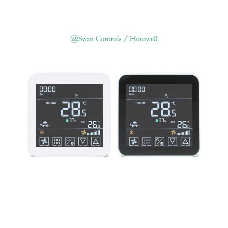
For a 2-pipe FCU project that needs 0–10V valve control, Modbus communication, and external sensor support, the HTW-WF11-FC-MEN (← please click it directly) is a relevant product direction.
Mistake 3: Treating EC Fan Control Like Standard 3-Speed Fan Control
A standard 3-speed fan and an EC fan are controlled differently.
A traditional digital thermostat may use relay outputs for low, medium, and high fan speed. This works for many AC fan coil units. But an EC fan often needs a 0–10V control signal. If the wrong digital thermostat is used, the fan may not run correctly.
This mistake is common because both systems may be called “fan coil control.” But the signal type is different.
Common complaints include:
- Fan speed cannot be adjusted smoothly.
- The fan only runs at one speed.
- The fan does not respond to the thermostat output.
- The room feels noisy or uncomfortable.
- The expected energy-saving effect is not achieved.
For EC fan projects, buyers should confirm the fan control signal before the sample order. They should also check whether the thermostat needs 24V power, 0–10V fan control, 0–10V valve control, or BMS communication.
For projects that need EC fan control and 0–10V valve control, this model HTW-WF11-FVM (← please click it directly) is a more suitable product direction.
Mistake 4: Ignoring Sensor Position and External Sensor Needs
A digital room thermostat can only control correctly when it reads the room temperature correctly.
If the thermostat is installed in the wrong place, the reading may not reflect the real room condition, even when wiring and output are correct.
Bad installation positions include:
- Near a door or window
- In direct sunlight
- Close to a supply air outlet
- On an external wall
- Behind curtains or furniture
- Near heat sources or poor air circulation
When the sensor reads a false temperature, the digital thermostat may stop too early, run too long, or switch modes too often.
Common complaints include:
- “The room is too cold, but the digital thermostat shows 24°C.”
- “The room is too hot, but the thermostat has already stopped cooling.”
- “The system turns on and off too often.”
- “Different rooms feel different even with the same setting.”
- “The customer says the thermostat is inaccurate.”
In some projects, an external sensor is better than relying only on the built-in sensor, especially when the digital room thermostat cannot be installed in an ideal location.
For projects that need remote sensing, Modbus communication, and 0–10V valve control, the HTW-WF11-FC-MEN (← please click it directly) can support this type of application.
The thermostat location affects how well the unit reads the real room condition. Placement also matters for energy use and comfort.

Mistake 5: Not Confirming Modbus or BACnet Data Points Before BMS Integration
For BMS projects, it is not enough to say “Modbus supported” or “BACnet supported.”
The buyer, contractor, and BMS integrator should confirm data points before ordering. Otherwise, the digital thermostat may support the protocol, but the BMS still cannot read or write required values.
Important points include address, baud rate, register list, object list, read/write permission, room temperature, setpoint, mode, fan speed, valve output, occupancy, keycard status, and alarm data.
Common complaints include:
- BMS cannot read the room temperature.
- BMS can read data but cannot write the setpoint.
- Fan speed or occupancy status is missing.
- Site commissioning takes longer than expected.
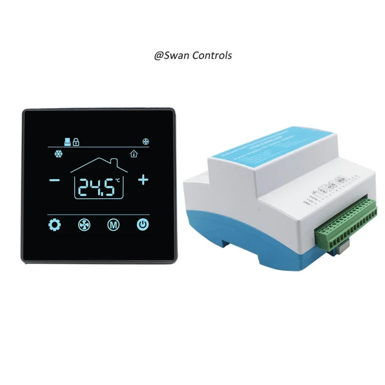
For BACnet hotel room thermostat projects, these two thermostats HTW-31-F10-2B/4B (← please click it directly) can be used when the project needs 2-pipe or 4-pipe FCU control and BMS integration.

Mistake 6: Choosing a Standalone Thermostat When the Project Needs Central Control
A standalone digital room thermostat can be the right choice for simple projects.
The problem happens when a buyer chooses a standalone digital room thermostat for a project that actually needs central control, keycard logic, Modbus, BACnet, or BMS monitoring.
A standalone 2-pipe room thermostat is often suitable for simple fan coil control, local room control, small offices, apartments, projects without BMS, and cost-sensitive applications.
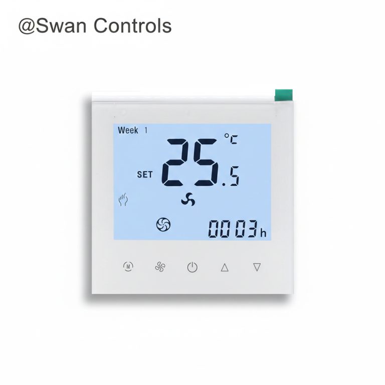
For this type of project, a standalone 2-pipe fan coil thermostat such as HTW-WF08-FC-2 standalone 2 pipe room thermostat (← please click it directly) can be a practical option.
But for hotels, serviced apartments, office buildings, or BMS projects, the buyer should not choose standalone control too quickly.
Common complaints include:
- The digital room thermostat cannot connect to BMS.
- Keycard energy-saving logic is not available.
- The buyer has to replace the room thermostat after installation.
The better decision logic is simple: standalone is fine when the room only needs local control. If the project needs BMS, keycard, central monitoring, or protocol integration, choose a communication model from the start.
Mistake 7: Overlooking Heating Load in Electric Heating Projects
For digital heating thermostats, one of the most common mistakes is ignoring the heating load.
Electric heating projects are not only about Wi-Fi, display design, or app control. The buyer must confirm whether the digital thermostat relay matches the real heating load.
For electric underfloor heating, buyers should check rated current, heating cable power, voltage, floor sensor support, maximum floor temperature, wiring safety, and whether a contactor is needed for larger loads.
Common complaints include:
- Heating is slow.
- Floor temperature is unstable.
- The relay is overloaded.
- The customer worries about safety.
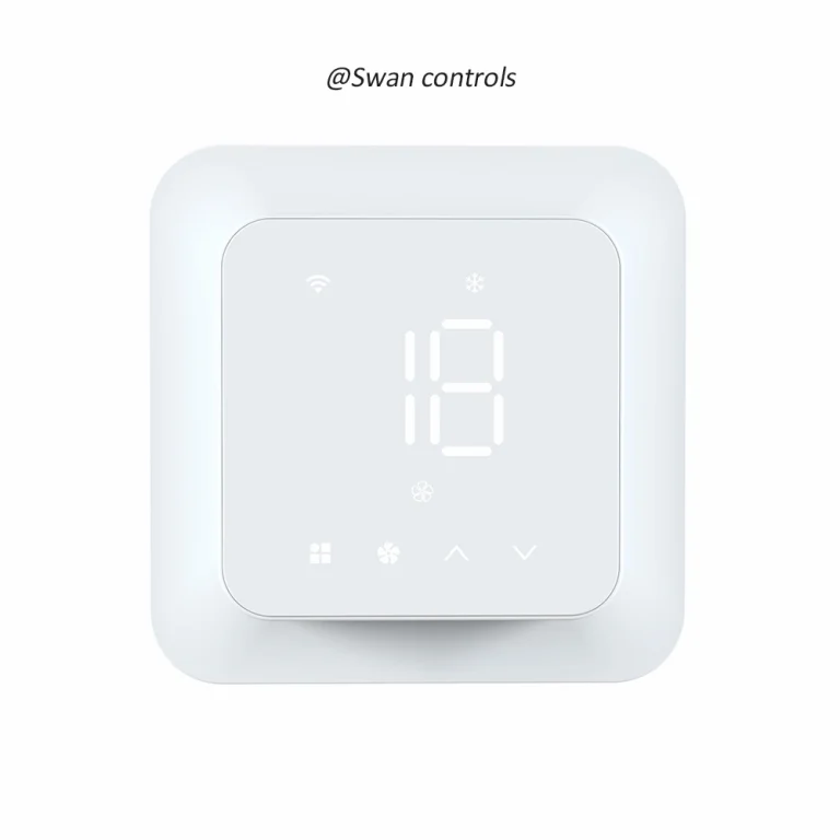
For residential electric underfloor heating projects, a 16A electric heating room thermostat such as HTW-HT09-16A3 (← please click it directly) can be used when the load and wiring conditions match the project requirement.
For heating projects, the buyer should never treat the app as the main control guarantee. Load, sensor, and safe wiring matter more than the display.

Mistake 8: Treating Wi-Fi as a Control Solution
Wi-Fi is useful, but Wi-Fi is not the control logic.
A Wi-Fi digital thermostat can allow remote operation, app scheduling, or voice assistant integration. But it does not automatically mean it is suitable for the HVAC system.
A buyer may choose a Wi-Fi thermostat because it looks modern. But if the output type, fan control, valve control, heating load, or sensor logic is wrong, the customer will still complain.
Common complaints include:
- The app can connect, but the room temperature is unstable.
- The valve does not respond correctly.
- The fan does not follow the expected logic.
- The installer cannot match the wiring with the equipment.
ENERGY STAR reports that certified smart thermostats can save about 8% of heating and cooling bills, or around $50 per year. But this depends on correct system matching, installation, and use.
Quick Diagnosis Table: Mistake, Complaint, Cause, and Check Point
| Common Mistake | Customer Complaint | Likely Cause | What to Check |
|---|---|---|---|
| 2-pipe/4-pipe logic not confirmed | Heating or cooling does not work correctly | Wrong valve or mode logic | FCU type, pipe type, valve output |
| Relay output used for 0–10V system | Valve does not modulate | Output signal mismatch | On/off vs 0–10V control |
| EC fan treated as 3-speed fan | Fan speed cannot adjust smoothly | Wrong fan signal | EC fan 0–10V requirement |
| Bad sensor position | Room temperature feels wrong | Sensor reads false temperature | Installation location, external sensor |
| BMS points not confirmed | BMS cannot read or write data | Missing register/object mapping | Modbus register or BACnet object list |
| Standalone model used for central control project | Cannot connect to BMS or keycard system | Wrong control level | Local control vs central integration |
| Electric heating load ignored | Heating unstable or relay overloaded | Load exceeds rating | Current, voltage, floor sensor |
| Wi-Fi treated as the main requirement | App works but control is wrong | System mismatch | Output, wiring, load, control logic |
Use this table before sample testing. It helps buyers, contractors, and thermostat suppliers find the likely cause before blaming the screen, app, or appearance.
Practical Case 1: Hotel Room with Wrong FCU Logic
A hotel project needs FCU control, keycard input, and BMS connection. The buyer first chooses a thermostat only by appearance and price.
During commissioning, the room control does not match the hotel sequence. The keycard logic is unclear, and the BMS integrator asks for BACnet points that were not confirmed before ordering.
The problem is not simply “bad thermostat quality.” The buyer did not confirm 2-pipe or 4-pipe logic, keycard function, and BACnet data points before approval.
A better direction is to test a BACnet 2/4 pipe FCU room thermostat with keycard (← please click it directly) before bulk order.
Practical Case 2: Office FCU with EC Fan and Modulating Valve
An office project uses EC fan coil units and a modulating valve. The buyer asks for a standard room thermostat because the front panel looks similar.
After installation, fan speed is not smooth, and room temperature fluctuates. The valve also does not respond as expected.
The real issue is output mismatch. The EC fan and modulating valve need suitable 0–10V control, while a basic room thermostat relay model may not provide the correct signal.
A better direction is to confirm 0–10V fan control, 0–10V valve control, voltage, and communication needs before ordering: HTW-WF11-FVM 24V EC fan thermostat with 0–10V valve control (← please click it directly).
How Suppliers Can Help Prevent Customer Complaints
A good digital thermostat supplier should not only send a quotation. It should help the buyer reduce project risk before ordering.
A professional supplier should ask:
- What system will the digital room thermostat control?
- Is it FCU, EC fan, PICV, boiler heating, or electric heating?
- Is the project 2-pipe or 4-pipe?
- What voltage is required?
- What output type is needed?
- Does the project need Modbus or BACnet?
- Will the order need OEM, custom, or wholesale support?
For overseas buyers, these questions are useful. They help avoid wrong control, installation delay, customer complaints, and replacement cost.
Scientific Data and Technical Reference Points
Digital thermostat performance is part of wider HVAC comfort and energy control. The International Energy Agency reports that space cooling energy use has more than tripled since 1990, making correct HVAC control more important in offices, hotels, apartments, and commercial buildings.
ASHRAE Standard 55 focuses on thermal environmental conditions for human occupancy. It considers temperature, humidity, air speed, radiant temperature, clothing, and activity level. This means room comfort is not only about the number shown on the thermostat.
| Technical Point | Practical Meaning | Why It Matters |
|---|---|---|
| Temperature reading | The room thermostat must sense the real room condition | Poor sensor location causes wrong control |
| 2-pipe / 4-pipe logic | Different FCU systems need different valve logic | Wrong logic causes heating/cooling complaints |
| 0–10V control | Used for EC fan, modulating valve, or PICV projects | Relay output cannot replace proportional control |
| Modbus/BACnet data | BMS needs defined points to read and write | Missing points delay commissioning |
| Electric heating load | Heating load must match relay rating | Overload can cause safety and reliability issues |
| Thermostat setback | Correct setback can reduce heating/cooling energy use | Useful for hotel and residential energy-saving logic |
FAQ
Why does my digital thermostat power on but not control the HVAC system correctly?
A digital thermostat may power on normally but still fail to control the system if the output type, wiring, voltage, fan type, valve type, or communication setting is wrong. Power-on only confirms that the display works. It does not confirm that the digital thermostat matches the HVAC equipment.
Why does the room temperature feel wrong even when the thermostat shows the correct setpoint?
The digital room thermostat sensor may not be reading the real room condition. Common causes include poor digital thermostat location, direct sunlight, nearby supply air, external wall installation, or missing external sensor support. In some projects, an external sensor is needed for more accurate room temperature control.
Why can’t the BMS read data from a Modbus or BACnet thermostat?
The BMS may not read data correctly if the register list, object list, baud rate, address, read/write point, or protocol mapping was not confirmed before commissioning. Buyers should request complete Modbus or BACnet documents before ordering.
What is the difference between 3-speed fan control and EC fan control?
A 3-speed fan is usually controlled by relay outputs for low, medium, and high speed. An EC fan often requires a 0–10V signal for speed control. These two control methods are different, so buyers must confirm the fan type before choosing a digital room thermostat.
Can Wi-Fi solve thermostat control problems?
No. Wi-Fi only provides remote operation or app control. It does not solve wrong wiring, wrong output type, wrong voltage, wrong load rating, or wrong system logic. The digital thermostat must first match the HVAC or heating system before Wi-Fi features become useful.
Final Note / Practical Takeaway
Most digital thermostat complaints are preventable.
The key is not only to choose a nice display or a low price. Buyers should confirm the real control logic before ordering. For FCU projects, this means checking 2-pipe or 4-pipe logic, fan type, valve output, 0–10V control, Modbus, BACnet, keycard function, and sensor location. For heating projects, this means checking electric load, floor sensor, voltage, wiring safety, and app logic.
A good digital room thermostat should make room control easier, not create extra problems for the installer or customer. If the supplier can help confirm system type, wiring, output, protocol, and sample testing before bulk order, the risk of wrong control and customer complaints will be much lower.
References / Sources
- U.S. Department of Energy, “Programmable Thermostats.” https://www.energy.gov/energysaver/programmable-thermostats
- ENERGY STAR, “Smart Thermostat Savings and Energy Efficiency Guidance.” https://www.energystar.gov/products/smart_thermostats
- ASHRAE, “BACnet™, the ASHRAE Building Automation and Control Networking Protocol.” https://www.ashrae.org/technical-resources/bookstore/bacnet
- BACnet International, “About the BACnet Standard.” https://bacnet.org/about-bacnet-standard/
- Modbus Organization, “Modbus Organization.” https://www.modbus.org/
- ASHRAE, “Standard 55: Thermal Environmental Conditions for Human Occupancy.” https://www.ashrae.org/technical-resources/bookstore/standard-55-thermal-environmental-conditions-for-human-occupancy
- International Energy Agency, “Space Cooling.” https://www.iea.org/energy-system/buildings/space-cooling
- U.S. Energy Information Administration, “Use of Energy Explained: Energy Use in Homes.” https://www.eia.gov/energyexplained/use-of-energy/homes.php
- U.S. Energy Information Administration, “Most Homes Have Central Thermostats on Heating and Cooling Equipment.” https://www.eia.gov/todayinenergy/detail.php?id=58439
- International Energy Agency, “Energy Efficiency 2023.” https://www.iea.org/reports/energy-efficiency-2023
Copyright © Swan Controls. All rights reserved. This article is written and published by Swan Controls. The content may not be copied, rewritten, or reused for commercial purposes without permission.
For product selection or project support, please feel free to get in touch with Swan Controls.