Quick Summary
A wireless thermostat still needs careful wiring checks, because the receiver is connected to the HVAC equipment. Before wiring, installers should confirm receiver output, voltage, load type, dry contact needs, relay rating, thermostat placement, pairing method, and signal range. A wireless room thermostat reduces control wiring in the room, but it does not remove the need for correct receiver installation. Good preparation prevents wrong control, product damage, and customer complaints.
“The room thermostat is wireless, so do we still need wiring?”
“Where should the receiver be installed?”
“Can we connect the receiver directly to the boiler, valve, or fan coil unit?”
These are common questions before installing a wireless thermostat. Many people think wireless means no wiring at all. This is not correct. The room unit may communicate wirelessly, but the receiver still needs correct wiring to the HVAC equipment.
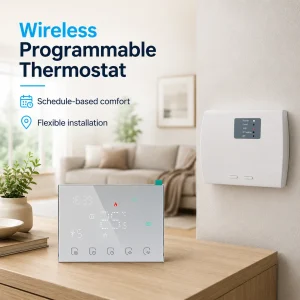
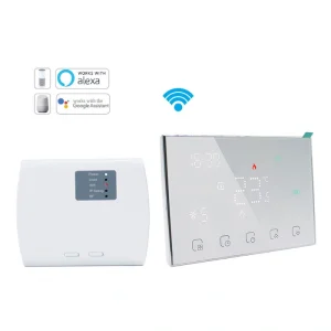
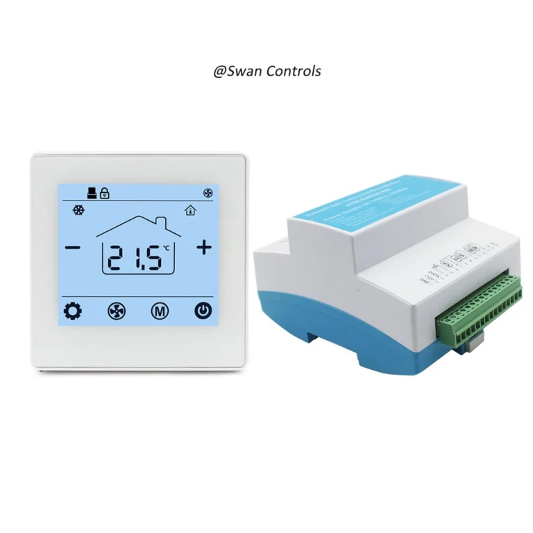
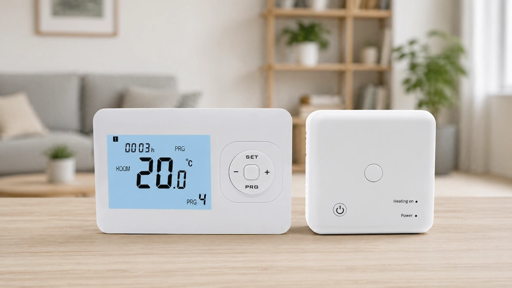
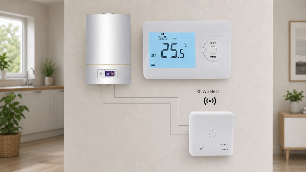
A wireless room thermostat is usually made of two parts. One part is placed in the room and senses temperature. The other part is the receiver, which connects to the boiler, valve, fan coil unit, or heating equipment. If the receiver wiring is wrong, the whole system may fail.
This guide explains what must be confirmed before wiring a wireless thermostat. It is written for installers, overseas buyers, HVAC distributors, and project contractors who want safer installation and fewer after-sales issues.
Confirm the Thermostat System Structure First
Before wiring, installers must understand the full system structure. A wireless thermostat is not only a wall-mounted display. It is a control system with a room unit and receiver.
The room unit measures temperature and sends wireless commands. The receiver receives the command and switches the connected HVAC equipment. This means the receiver is the wiring point, not usually the room thermostat.
Basic system structure:
- Room thermostat: temperature sensing and user operation
- Receiver: wireless signal receiving and output switching
- HVAC equipment: boiler, valve, heating system, or fan coil unit
- Power supply: for receiver and sometimes for room unit
- Load output: dry contact, relay, valve output, or other control output
This structure should be clear before any cable is connected. If the installer treats the wireless room unit like a wired thermostat, wrong wiring may happen.
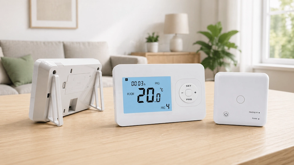
For buyers, this is also important. Product pages should show both the thermostat and receiver. Manuals should explain which part is wired and which part is wireless. This reduces confusion for installers and end users.
Confirm the HVAC Application Before Wiring
The receiver wiring depends on the HVAC application. A wireless thermostat used for boiler heating is not wired the same way as one used for valve control or fan coil control.
Before wiring, confirm the real application:
- Boiler heating
- Water heating system
- Electric heating system
- Underfloor heating
- Fan coil unit system
- Zone control system
- Valve actuator control
For boiler heating, many systems require dry contact output. The receiver only acts like a switch. It should not send the wrong voltage into the boiler control terminal.
For valve control, the installer must check actuator voltage and open/close logic. Some valves need normally open control. Some need normally closed control. Some require powered output.
For fan coil unit projects, wiring may include fan speed and valve output. This is more complex than basic boiler control. A wireless thermostat must be selected and wired according to the actual FCU logic.
The safest step is to compare three documents before wiring:
- HVAC equipment wiring diagram
- Wireless thermostat receiver wiring diagram
- Project control requirement
Confirm Receiver Output Type
The receiver output is one of the most important installation points. It decides how the HVAC equipment receives the control command.
Common receiver output types include:
- Dry contact output
- Powered relay output
- Normally open output
- Normally closed output
- Valve control output
- Fan or auxiliary output, depending on model
Dry contact output is common in boiler control. It works like a switch and does not supply voltage. Powered output is different. It may send voltage to a valve or load.
Installers must not guess this point. A wrong output can damage equipment or stop the system from working.
| Output Type | Common Use | Before Wiring |
|---|---|---|
| Dry contact | Boiler enable / heating demand | Confirm no voltage should be supplied. |
| Powered relay output | Valve or load switching | Confirm output voltage and load current. |
| Normally open | Starts load when relay closes | Check system start logic. |
| Normally closed | Stops load when relay opens | Check fail-safe and actuator logic. |
For overseas buyers, this part should be made clear in product documents. Installers in different countries may use different wiring habits. A clear terminal table reduces mistakes.
Confirm Voltage and Power Supply
Voltage must be confirmed before wiring. A wireless thermostat receiver may use 24V, 110V, 220V, or 230V depending on the model and market.
Incorrect voltage can damage the receiver immediately. It can also create safety risk.
Installers should check:
- Receiver power supply voltage
- Room thermostat power method
- Output voltage, if powered output is used
- HVAC equipment control voltage
- Local mains voltage
- Neutral wire requirement
- Grounding requirement, if applicable
For battery-powered wireless room thermostats, the room unit may not need mains wiring. But the receiver still needs power. If the receiver is installed near the boiler or equipment, its power source must be safe and stable.
Installers should never connect the receiver only by wire color. Wire colors may differ by market or project. Terminal labels and wiring diagrams are more reliable than color assumptions.
Confirm Relay Load and Equipment Current
The receiver relay must match the connected load. This is often ignored during installation.
The relay may control a boiler input, valve actuator, pump, fan, or heating load. Each load has a different current requirement. Some loads are resistive. Some are inductive. Inductive loads can be harder on relay contacts.
Before wiring, confirm:
- Relay current rating
- Load current
- Load type: resistive or inductive
- Startup current, if applicable
- Electrical life of relay
- Whether an external contactor is needed
If the connected load is too high, the receiver relay may fail early. In some cases, the thermostat may work during testing but fail after several weeks or months.
For higher loads, it may be safer to use the receiver to control an external relay or contactor. This reduces stress on the receiver relay and improves long-term reliability.
Choose the Receiver Location Carefully
The receiver location affects both wiring and wireless signal.
It should be close enough to the HVAC equipment for safe wiring. It should also be positioned where it can receive stable wireless signal from the room thermostat.
Poor receiver locations include:
- Inside metal cabinets
- Behind thick concrete walls
- Beside high-power electrical panels
- Very close to motors or pumps
- Too far from the room thermostat
- Low positions blocked by furniture or equipment
Good receiver placement should allow:
- Safe wiring access
- Clear signal path where possible
- Easy service access
- Visible status indicator
- Simple reset or pairing operation
This is important in boiler rooms, mechanical rooms, and utility areas. A receiver hidden too deeply may be hard to check later. If the status light cannot be seen, troubleshooting becomes slower.
Choose the Room Thermostat Position Before Pairing
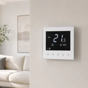
The room thermostat position should be selected before final pairing and testing. A wireless room thermostat is flexible, but it still needs correct placement.
The room unit should sense the real room condition. It should not be placed near heat, cold air, or direct sunlight.
Avoid these locations:
- Near windows
- Under direct sunlight
- Near radiators or heaters
- Near supply air outlets
- Behind curtains
- Behind furniture
- Near doors with frequent drafts
Better placement:
- Central room area
- About 1.2 m to 1.5 m above the floor
- Away from direct heat sources
- Away from strong airflow
- Easy for users to see and operate
Correct placement improves both temperature accuracy and user experience. A wireless thermostat gives more freedom than a wired model, so installers should use that freedom properly.
Test Wireless Signal Before Final Wiring
Signal testing should be done before the receiver is fixed permanently.
Do not only test the thermostat and receiver on a desk. Desk testing only confirms that the two devices can communicate in easy conditions. It does not prove that they will work in the real building.
Before final wiring, test:
- Signal from final thermostat position
- Signal through closed doors
- Signal through one or more walls
- Signal near boiler or equipment room
- Signal when receiver cover is installed
- Signal after other electrical equipment is running
This step is especially important in villas, apartments, and buildings with concrete walls. Signal loss can cause delayed response or intermittent control.
Installers should also check whether the receiver has a signal indicator. If it does, confirm the indicator status after the thermostat sends a command.
Pair the Thermostat and Receiver Correctly
Pairing should be completed before final handover. In multi-room projects, pairing must be done carefully.
Recommended pairing process:
- Pair one thermostat and one receiver at a time
- Label each room thermostat
- Label each receiver
- Confirm signal response after pairing
- Record the room name or zone number
- Test heating or cooling demand
- Test stop command
In apartment or villa projects, pairing confusion can create serious complaints. One thermostat may control the wrong receiver. A bedroom thermostat may start heating in the living room. This is difficult for end users to understand and very costly to fix later.
Clear labelling is simple but effective. It should be part of standard installation practice.
Confirm Battery and Memory Settings
If the wireless room thermostat is battery powered, battery checks are necessary before handover.
Installers should confirm:
- Battery type
- Battery direction
- Battery contact condition
- Low-battery warning
- Expected battery life
- Whether settings are saved after battery replacement
- Whether pairing is kept after battery replacement
Battery problems may appear as control problems. A weak battery can reduce transmission strength. It may also cause display problems or delayed response.
For rental, hotel, or commercial projects, battery maintenance should be explained to the facility team. If battery replacement is ignored, after-sales complaints may appear later.
Scientific Data
The data below gives practical reference values for wireless thermostat installation. These values help installers and buyers judge whether the product and installation are suitable. Actual performance depends on building material, receiver design, load type, battery quality, and installation position.
| Installation Item | Typical Reference Value | Installation Meaning |
|---|---|---|
| Recommended thermostat height | 1.2 m to 1.5 m above floor | Helps sense normal occupied-zone temperature. |
| Open-area wireless range | 50 m to 100 m possible | Best-case value only. |
| Typical indoor wireless range | 20 m to 30 m | More realistic for homes and apartments. |
| Signal loss through walls | 30% to 70% range reduction | Concrete and metal can reduce signal strongly. |
| Temperature accuracy | ±0.5°C to ±1.0°C | Supports stable comfort control. |
| Poor placement temperature error | 2°C to 3°C possible | Sunlight or airflow can create false readings. |
| Battery life reference | 6 to 24 months by model | Maintenance plan may be needed. |
| Relay mechanical life | 100,000 to 1,000,000 cycles | Affects long-term receiver reliability. |
| Common relay rating range | 3A to 16A by model | Must match the controlled load. |
| Quiet room fan noise reference | 30 dB to 45 dB | Useful when controlling FCU or fan systems. |
These values show why installation position matters. A thermostat installed near sunlight may show a wrong room temperature by 2°C to 3°C. This can make the HVAC system stop too early or run too long.
Wireless range also needs realistic testing. An open-area range of 100 m does not mean the same range inside a concrete building. Indoor range is usually lower. Walls, floors, and metal parts can reduce signal strength.
Relay rating must be matched to the real load. If the relay is too small, output contacts may wear faster. For larger loads, an external relay or contactor may be needed.
Battery life should also be considered before handover. In commercial or rental projects, a clear battery maintenance plan can reduce service calls.
Final Wiring and Function Test
After wiring is complete, installers should test the full control chain. This test should include the room thermostat, receiver, and HVAC equipment.
Do not stop after the display turns on. A working display does not prove correct control.
Final test steps:
- Check receiver power
- Check thermostat display
- Confirm pairing status
- Raise setpoint to create heating demand
- Check receiver relay response
- Confirm HVAC equipment starts
- Lower setpoint to stop demand
- Confirm HVAC equipment stops
- Test manual override if available
- Record final installation position
This step helps catch wiring errors before the user starts using the system. It also gives the installer confidence that the complete system is working.
If you‘re Looking for related products, kindly check the following details:
Electric Underfloor Thermostat
Practical Cases
Case 1: A boiler project used a wireless thermostat, but the boiler did not start during testing. The installer found that the receiver was connected to the wrong terminals. After checking the dry contact diagram, the wiring was corrected and the boiler worked normally.
Case 2: In a villa project, the receiver was first installed inside a metal cabinet. Pairing worked during desk testing, but signal became unstable after final installation. The receiver was moved to a better position. The wireless control became stable.
Case 3: An apartment room had unstable temperature control. The wireless room thermostat was placed near a window. Sunlight caused a false high reading. After moving the thermostat to an inner wall, the temperature control became more accurate.
These cases show that installation basics are not small details. They decide whether the wireless thermostat works well in real use.
Expert Insights
Wireless thermostats are popular because they reduce wiring work. This is valuable for finished homes, retrofit projects, apartments, villas, and boiler heating systems.
However, wireless thermostat’s wireless installation still needs discipline. The receiver must be wired correctly. The room unit must be placed correctly. Pairing must be tested. Signal range must be checked in real conditions.
For overseas buyers, installation documents are part of the product value. A good wireless thermostat supplier should provide wiring diagrams, receiver output details, pairing steps, signal range information, and troubleshooting guidance.
For contractors, the best practice is to test before final fixing and test again after wiring. This reduces callbacks and protects project quality.
Pre-Wiring Checklist
| Check Point | Why It Matters | Before Wiring |
|---|---|---|
| System application | Different systems need different outputs. | Confirm boiler, valve, heating, or FCU. |
| Receiver output | Wrong output causes wrong control. | Check dry contact, relay, NO/NC logic. |
| Voltage | Wrong voltage can damage the product. | Confirm receiver power and load voltage. |
| Relay rating | Load mismatch shortens service life. | Compare relay rating with real load. |
| Receiver location | Affects wiring and signal. | Avoid metal cabinet and electrical noise. |
| Thermostat position | Affects temperature accuracy. | Avoid sunlight, airflow, and heat sources. |
| Pairing | Wrong pairing causes wrong room control. | Pair and label one set at a time. |
| Signal range | Weak signal causes unstable control. | Test in final position before fixing. |
This checklist helps installers avoid the most common wiring and setup problems. It is also useful for buyers who want to evaluate whether a supplier provides enough installation support.
FAQ
1. Does a wireless thermostat still need wiring?
Yes. The room thermostat may be wireless, but the receiver still needs wiring to the HVAC equipment and power supply.
2. What should be confirmed before wiring a wireless thermostat?
Installers should confirm application, receiver output, voltage, relay rating, wiring diagram, thermostat position, pairing method, and signal range.
3. Where should the receiver be installed?
The receiver should be near the HVAC equipment, easy to access, and placed away from metal cabinets, thick walls, and strong electrical interference.
4. Can a wireless room thermostat be placed anywhere?
No. It should be placed away from sunlight, airflow, radiators, windows, doors, and blocked locations to avoid wrong temperature readings.
5. Why should signal range be tested before final wiring?
Signal range should be tested because real walls, floors, doors, and electrical equipment can reduce wireless communication performance.
Wireless thermostat installation should start with confirmation, not wiring. The installer should check receiver output, voltage, relay load, thermostat position, signal range, pairing, and system type before connecting cables. A wireless room thermostat can reduce room-side wiring, but correct receiver wiring and full-system testing are still essential for safe and stable HVAC control.
References / Sources
- International Electrotechnical Commission (IEC) — IEC 60730 Automatic Electrical Controls for Household and Similar Use
- Federal Communications Commission (FCC) — Radio Frequency Devices Compliance Guidance
- European Telecommunications Standards Institute (ETSI) — Short Range Devices Technical Guidance
- Radio Equipment Directive (RED) — Wireless Product Compliance Requirements
- UL Standards — Electrical Control and Switching Device Safety References
- CSA Group — Electrical Product Certification and Control Device Guidance
- Intertek — Wireless Product Testing and Certification Resources
- TÜV SÜD — Radio Equipment and Wireless Device Testing Guidance
- Honeywell Home — Wireless Thermostat Installation and Pairing Guides
- Danfoss — Room Thermostat and Heating Control Technical Publications
- Siemens Building Technologies — Room Thermostat and HVAC Control Literature
- General HVAC Receiver Wiring and Room Control Installation References