“The thermostat is online, but the project team still says communication is not right. Why?”
“Because in a Modbus thermostat project, communication is never only about one wire or one screen. The network, the gateway, the addressing, the register map, and the FCU control logic all need to match.”
That is where many HVAC projects become confusing. A buyer may select a Modbus thermostat because the building needs central visibility. The installer may connect the RS485 bus correctly. The BMS team may confirm that devices are visible on the network. But later, the project still feels unstable. Fan speed does not respond as expected. Cooling and heating logic looks wrong. Setpoint values can be read, but the real room behavior still does not match what the operator wants. When this happens, people often say there is a “Modbus problem.” In reality, the problem is usually broader. It often starts with communication design, not only with the thermostat itself.
This is why a communication guide is necessary. A Modbus thermostat is not just a room thermostat with extra terminals. It is part of a wider control structure. In FCU systems, especially in 2-pipe, 4-pipe, 0–10V modulating, and PICV-related projects, communication must align with control logic. If the network structure is not clear, if the gateway role is misunderstood, or if the register plan does not match the actual project behavior, the thermostat may still power on and still fail to create a usable system. This article explains the full communication picture in a practical way: what the network really means, what the gateway really does, how control logic changes the communication value, and how to avoid the most common mistakes before the project reaches site.
Quick Summary: The 4 Communication Layers Buyers Should Understand First
Most Modbus thermostat communication questions become clearer when buyers separate the project into four layers. The first layer is the physical communication path, usually RS485 in serial Modbus thermostat projects. The second layer is the protocol layer, where Modbus RTU or related communication settings define how devices talk. The third layer is the integration layer, where gateways or BMS platforms collect, translate, or supervise room data. The fourth layer is the control layer, where the thermostat’s actual FCU logic decides what the data really means in practice. If one of these layers is misunderstood, the whole system can look connected while still behaving badly.
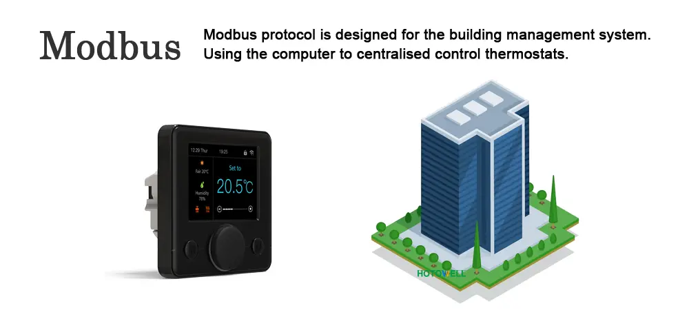
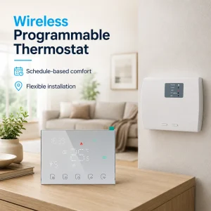
What a Modbus Thermostat Really Communicates
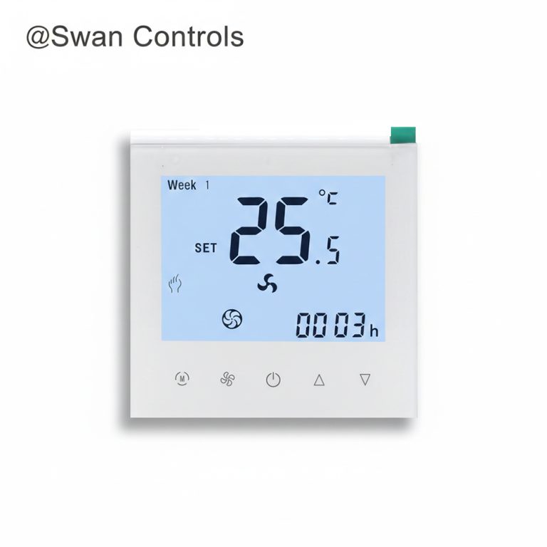
A Modbus thermostat is usually described too simply. Many people say it is just a room thermostat with Modbus. That is true, but incomplete. In practice, a Modbus thermostat is a room thermostat that can exchange defined data with a wider system. That data may include room temperature, setpoint, fan speed command, operating mode, valve state, alarm-related status, and other project-level points depending on the product design.
This distinction matters because local control and communication control are not the same thing. A local room thermostat can still perform perfectly from the user’s point of view without telling a wider system anything. A Modbus thermostat adds another layer of value: it can become visible to a supervisory structure. That is why it is often chosen for offices, hotels, managed apartments, or commercial spaces where room-by-room data matters more than isolated wall control alone.
In practical FCU projects, this means a thermostat is no longer only a comfort device. It is also a data point, a command point, and sometimes a commissioning point. That is the real foundation of the communication guide.
Network Basics: Why RS485 Is Mentioned So Often
In most serial Modbus thermostat projects, the communication path is built around RS485. Buyers often say “Modbus thermostat” and “RS485 thermostat” almost interchangeably, but they are not the same term. Modbus is the communication protocol. RS485 is the common serial physical layer that carries the communication in many HVAC projects.
This distinction matters because a project can have the right protocol expectation and still fail at the physical layer. The wiring may be poor. The polarity may be inconsistent. The shielding may be weak. The common reference may be ignored. Or the network may simply be built in a way that creates unstable communication. When that happens, the thermostat may appear fine locally while the wider system sees intermittent data or no usable communication at all.
From a buyer’s point of view, the practical lesson is simple: when a supplier says the thermostat supports Modbus, the next question should be how that communication is physically delivered in the project. In many FCU projects, that answer is RS485 Modbus RTU. If that is not made explicit, confusion begins very early.
| Term | Meaning | Project Relevance |
|---|---|---|
| Modbus | Communication protocol | Defines how data is structured and exchanged |
| RS485 | Physical serial layer | Carries Modbus RTU communication in many thermostat projects |
| Modbus RTU | Common serial Modbus implementation | Typical format for FCU thermostat communication |
| Modbus TCP | Ethernet-based Modbus communication | Often appears through gateways or broader building networks |
Addressing, Serial Settings, and Why “Online” Is Not Enough
One of the most common misunderstandings in Modbus thermostat communication is assuming that device detection means the system is correctly integrated. It does not. A thermostat can be visible on the network and still be unusable in practical control.
There are several reasons. The first is addressing. In a standard Modbus network, every server device should have a unique address. If two thermostats share an address, the BMS or gateway may read unstable or confusing data. The second is serial settings. Baud rate, parity, and stop-bit settings must align across the thermostat, the communication controller, and the gateway or BMS interface. If these values do not match, the project may look partially online and still fail to communicate reliably. The third is timing and polling behavior. Even when devices are visible, the system may still be too poorly aligned to behave consistently.
For this reason, “online” should never be the final communication test in a real FCU project. The real test is whether the thermostat data can be read correctly, whether commands can be written correctly, and whether the physical FCU behavior matches the intended communication logic.
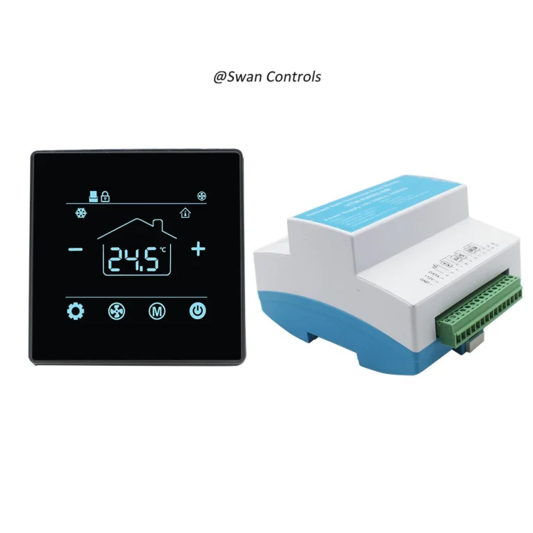
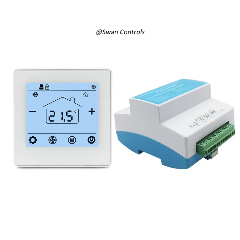
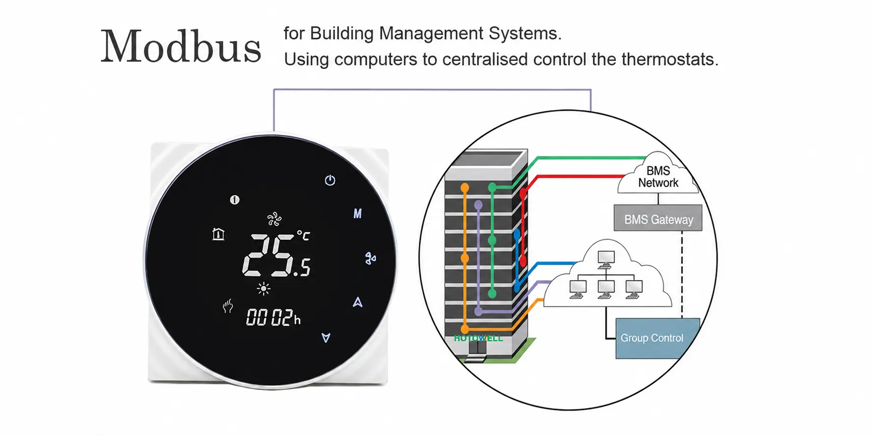
What a Gateway Actually Does in a Modbus Thermostat Project
Many buyers hear the word gateway and treat it like a small accessory. In reality, the gateway is often one of the most important communication components in a managed thermostat project. A gateway is not just a converter. It is the bridge that allows different communication layers or network structures to work together in one practical system.
In a typical building project, the thermostats may communicate through Modbus RTU over RS485, while the supervisory platform may operate through Ethernet or another higher-level network environment. The gateway becomes the connection point between the room devices and the wider system. This is why many communication failures are not purely thermostat failures. They are gateway expectation failures. The thermostat may expose data in one structure, while the gateway or BMS expects another. The result is not total silence. It is partial, confusing, or misleading communication.
That is why buyers should never ask only whether the thermostat supports Modbus. They should also ask how the thermostat will enter the real system. Direct serial bus? Gateway to BMS? Gateway to TCP network? The answer changes how the whole project should be planned.
Why Control Logic Matters as Much as the Network
Communication alone does not create a good Modbus thermostat project. The communication still needs to represent the right control behavior. This is where many projects go wrong. The network team may focus on addresses, baud rate, and polling, while the HVAC team assumes the thermostat logic is already correct. But if the thermostat is matched to the wrong FCU control structure, then even perfect communication will produce the wrong real-world result.
This is especially important in FCU systems. A 2-pipe project does not behave the same way as a 4-pipe project. A standard 3-speed fan project does not behave the same way as an EC fan or 0–10V modulating project. A PICV-related application brings another layer of output logic. If the communication points are technically readable but the thermostat’s internal control family does not match the real application, the BMS may still appear to work while the room behavior is wrong.
That is why communication guides should always include control logic. A thermostat project is not complete just because the network can see the device. It is complete when the network sees the right device and the device is controlling the right FCU behavior.
2-Pipe, 4-Pipe, 0–10V, and PICV: Why the Data Means Different Things
This is one of the most important parts of the guide because many buyers treat communication points as if they mean the same thing across all thermostat models. They do not. The control family changes the practical meaning of many points.
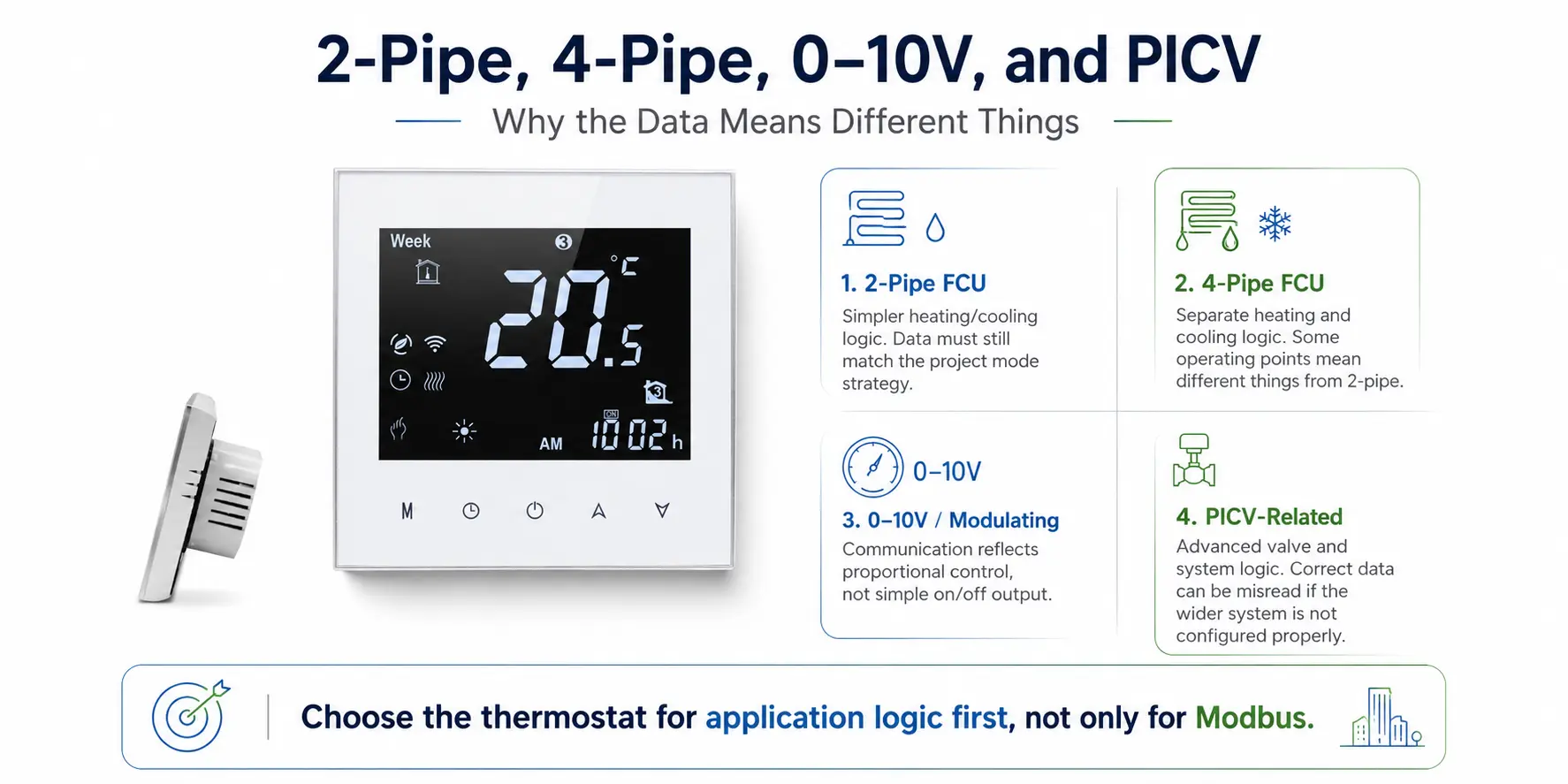
2-pipe FCU projects
In 2-pipe systems, the thermostat usually follows a simpler cooling or heating logic. The communication structure can therefore be more straightforward, but it still needs to match the actual project mode strategy.
4-pipe FCU projects
In 4-pipe systems, the thermostat handles separate heating and cooling logic. That changes not only the control behavior but also the meaning of some operational data. A project that assumes 2-pipe logic can therefore misread 4-pipe behavior even when communication is technically active.
0–10V or modulating projects
When the thermostat is designed for 0–10V or other modulating control, the communication points no longer reflect a simple on/off output strategy. The BMS team must understand that the thermostat is reporting and commanding a different control model.
PICV-related projects
PICV-related applications add another level of output and system logic. Buyers who ignore this often think the thermostat is not communicating correctly, when in fact the thermostat is communicating advanced control behavior that the wider system has not interpreted correctly.
This is why product selection should always start with real application fit. A model such as the indoor Modbus thermostat for 2-pipe fan coil unit system, the popular Modbus thermostat for 4-pipe fan coil unit systems, the FCU 3 fan speed 0–10V modulating thermostat with Modbus, the 24VDC output PICV thermostat with Modbus keycard energy saving, or the durable indoor BMS smart Modbus thermostat for 4-pipe FCU system should be chosen first for application logic, not only for the presence of Modbus communication.
| Control Family | What Changes in Communication | Why It Matters |
|---|---|---|
| 2-pipe | Simpler operation logic | More straightforward interpretation for basic FCU projects |
| 4-pipe | Separate heating and cooling logic | Wrong interpretation can create false “communication problems” |
| 0–10V / modulating | Advanced output meaning | BMS must read and use the data in the correct control context |
| PICV / 24VDC-related | Specialized control role | Communication only adds value if the project actually uses the logic |
How Buyers Should Think About Network Topology
One useful way to simplify Modbus thermostat communication is to think in topology rather than only in product names. A small project may have a direct serial bus with a limited number of thermostats. A medium project may use one or more gateways to connect room thermostats to a BMS. A larger project may separate floors or zones into communication branches and then unify them at management level.
Each topology changes the project question slightly. In a direct serial bus, wiring discipline and device addressing become more visible. In a gateway-based architecture, mapping logic and integration planning become more important. In larger structured projects, long-term maintainability often becomes as important as day-one commissioning.
This is why a communication guide should not stop at “the thermostat supports Modbus RTU.” Buyers should ask what the actual network path will look like in the building. That question usually reveals more about the right thermostat choice than a general feature checklist.
Common Communication Mistakes Buyers Make Early
- They assume “Modbus” automatically means “fully interoperable.”
- They treat RS485 as if it already defines the whole communication solution.
- They confirm physical wiring but not serial settings or address planning.
- They request communication but do not confirm how the gateway or BMS will use the data.
- They ignore FCU control type and focus only on protocol label.
- They test whether the thermostat is online, but not whether the real control behavior matches the project design.
These mistakes are common because the communication chain is longer than many buyers expect. A good thermostat alone does not solve a weak communication plan.

Expert Commentary: Communication Problems Usually Start Before Site Commissioning
Most project teams discover communication problems too late because they define “communication” too narrowly. They focus on whether the thermostat supports Modbus, but they do not define how the building will actually use that capability. They confirm protocol, but not network path. They confirm BMS interest, but not register logic. They confirm FCU type, but not how that changes what the data points mean.
This is why the best Modbus thermostat communication projects usually begin with a structured matching process. The thermostat, the network, the gateway, and the control family are reviewed together. Projects that do this early usually reach commissioning with less friction and fewer arguments between HVAC, electrical, and BMS teams.
Industry Trend: Why Communication Design Matters More as Buildings Become More Managed
As buildings become more managed and more data-aware, thermostat communication matters more. That does not always mean every room needs the most complex thermostat. It means that whenever a thermostat is expected to fit inside a managed system, the communication design needs to be treated as a real engineering layer, not just a feature checkbox.
This trend is especially strong in hotel, office, and larger commercial room-control projects, where centralized visibility and structured maintenance are part of normal expectations. In those environments, a thermostat that communicates badly is not a small inconvenience. It is a system management problem.
Scientific Data and What It Means
Several standard points from Modbus practice help explain why thermostat communication needs structure. Modbus is an application-layer protocol, not a physical bus standard. RS485 two-wire is one of the most common physical implementations used for Modbus serial communication. Standard Modbus serial networks typically rely on unique device addressing within the normal 1 to 247 server range. Modbus TCP commonly uses port 502 in Ethernet-based communication structures. These facts matter because they show that a thermostat project cannot be planned by product appearance alone. The communication path, addressing structure, and system architecture are all part of what makes the thermostat usable in a real FCU project.
Real Cases and User Feedback
Case 1: A 4-pipe project that looked like a communication fault
One office project reported that the Modbus thermostat was readable but “not working properly” from the BMS side. The root problem turned out not to be protocol failure. The project team had not aligned their expectations around 4-pipe heating and cooling logic, so the communication points were being interpreted through the wrong control model.
Case 2: A gateway project where the thermostat was correct but the path was unclear
In another project, the thermostat specifications were acceptable, but the gateway strategy had not been defined clearly enough in advance. Once the team reviewed how the data should pass from room devices into the supervisory system, the communication design became much easier to stabilize.
Case 3: A simpler 2-pipe project that succeeded because the communication plan stayed simple
Not every good project is highly complex. One successful FCU project used a straightforward 2-pipe control family and a clear Modbus communication structure. The result was stable because the project resisted the temptation to mix too many advanced assumptions into a system that did not need them.
User feedback pattern: Project teams rarely regret defining the communication path too clearly. They usually regret assuming the thermostat, gateway, and FCU logic would somehow align automatically once the site wiring was complete.

Frequently Asked Questions
1. What does a Modbus thermostat actually communicate?
A Modbus thermostat typically communicates room-level operating data such as temperature, setpoint, fan command, mode status, and other control points depending on the product design and FCU application.
2. Why is RS485 mentioned so often in Modbus thermostat projects?
Because many serial Modbus thermostat projects use RS485 as the physical communication layer. Modbus is the protocol, while RS485 is the common transport path in many HVAC applications.
3. What does a gateway do in a Modbus thermostat system?
A gateway connects the thermostat communication layer to a wider control or management structure, often linking serial thermostat devices to a BMS or Ethernet-based supervisory system.
4. Why can a Modbus thermostat be online but still not work properly in the project?
Because being online only proves partial communication. The project may still have wrong addressing, serial settings, gateway expectations, register mapping, or FCU control logic that does not match the actual thermostat design.
5. How can I avoid Modbus thermostat communication problems before ordering?
You should confirm the FCU control type, network path, serial settings, address plan, gateway role, and register logic before ordering or commissioning the project.
References / Sources
- Modbus Organization, Modbus Application Protocol Specification V1.1b3
- Modbus Organization, Modbus over Serial Line Specification and Implementation Guide V1.02
- Modbus Organization, Modbus Messaging on TCP/IP Implementation Guide V1.0b
- Modbus Organization, Specifications and Implementation Guides
- Modbus Organization, Introduction to Modbus
- Schneider Electric, SpaceLogic Thermostat – TH900 Series Thermostat – Installation Instructions
- Schneider Electric, Thermostats and Sensors
- Wikipedia, Modbus
- Wikipedia, RS-485
- Modbus Organization, About Us