Quick Summary
A digital thermostat is not matched only by screen design, Wi-Fi function, or communication protocol. For real HVAC and heating projects, the key question is whether the sensor input, relay capacity, and output type match the equipment being controlled.
A room thermostat may work well in one project but fail in another if the sensor location, valve signal, fan control, or heating load is different. This is why overseas buyers should confirm the input and output logic before asking for bulk price or approving samples.
This article focuses on digital fan coil thermostats and digital heating thermostats. It explains how to match built-in sensors, external sensors, floor sensors, relay outputs, dry contact, 0–10V output, EC fan control, on/off valves, PICV, boiler heating, and electric heating load.
When choosing the right thermostat, many buyers ask:
“We already know the system type. How do we determine the correct sensor, relay, or output type?”
The answer is straightforward:
“Please start with the equipment being controlled, not the thermostat’s appearance.”
If the system requires an external room sensor, a built-in sensor alone may not be sufficient. If the valve needs a 0-10V control signal, a relay-only model will not work properly. If the heating cable requires a 16A output, using a lower-rated unit may create safety and reliability issues.
Why Sensor, Relay, and Output Matching Matters
A digital thermostat is the control point between the user and the HVAC equipment. It reads temperature, compares it with the setpoint, and sends an output signal to fans, valves, compressors, boilers, or heating loads.
If the sensing side is wrong, the thermostat controls based on the wrong temperature. If the output side is wrong, the equipment cannot respond correctly. Both problems can lead to customer complaints.
Common symptoms include:
- Room temperature feels different from the displayed value.
- Fan speed does not respond correctly.
- Valve stays open or closed.
- EC fan cannot modulate.
- BMS can read the controller but cannot control the expected point.
- Floor heating overheats or responds too slowly.
- Boiler does not start because the interface type is wrong.
A room thermostat should be selected by checking three layers: sensor input, control output, and system logic. These layers should match before installation begins.
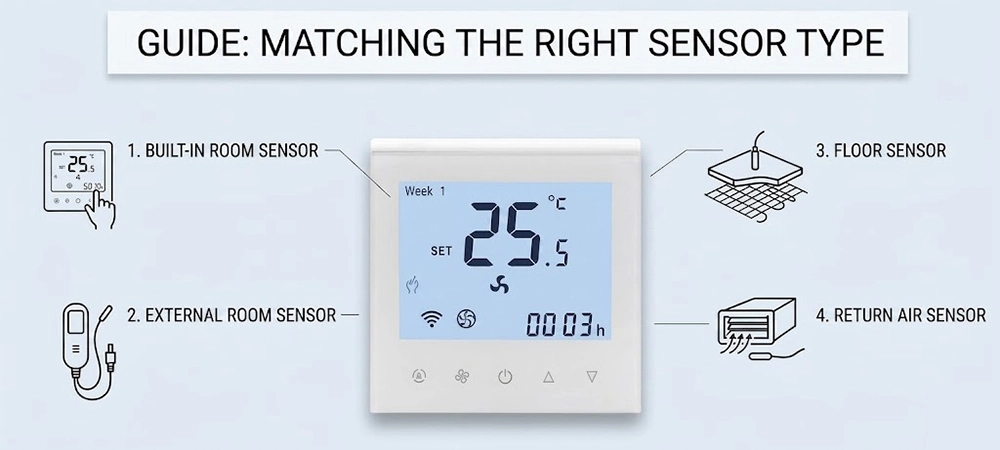
Matching the Right Sensor Type
Sensor selection is the first step. A digital thermostat can only control correctly if it measures the right temperature.
The most common sensor options are:
| Sensor Type | Typical Use | Key Risk If Wrong |
|---|---|---|
| Built-in room sensor | Standard room wall control | Wrong reading if installed in a poor location |
| External room sensor | Hotel, office, FCU, special wall layout | Added wiring and sensor placement must be planned |
| Return air sensor | Some HVAC or FCU systems | May not reflect occupied room temperature |
| Floor sensor | Electric floor heating | Floor overheating or poor heating protection if missing |
| Combined sensor logic | Heating systems with both room and floor limits | Incorrect setup may affect comfort or safety |
A digital thermostat with a built-in sensor is often enough for simple room control. But the wall location must be suitable. It should not be near direct sunlight, supply air, external walls, doors, windows, or heat-generating equipment.
An external sensor is useful when the controller must be installed in one location but the temperature should be measured in another place. This often happens in hotel rooms, commercial rooms, and FCU projects where appearance and wiring path affect controller position.
When to Use a Built-In Sensor
A built-in sensor is suitable when the thermostat can be installed in a representative room position.
This is common in apartments, offices, basic FCU rooms, and small commercial spaces. The installer should place the controller where air can move naturally around it. The height, wall type, nearby heat sources, and airflow should all be checked.
A room thermostat with a built-in sensor is a practical choice when:
- The wall location reflects the real occupied zone.
- There is no direct sunlight.
- There is no supply air blowing onto the controller.
- The wall is not unusually hot or cold.
- The project does not require remote sensing.
- The user needs simple local control.
The main advantage of built-in sensing is simple installation. The main limitation is that the reading depends heavily on the installation position.
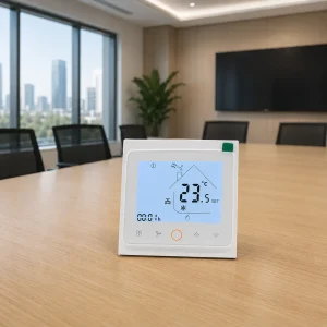
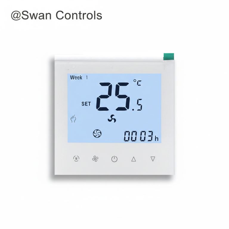
For simple 2-pipe FCU applications without BMS or special sensor needs, our model Swan Controls HTW-WF08-FC-2 might fit.
When an External Room Sensor Is Better
An external room sensor is better when the controller location is not the best sensing location.
This can happen in hotel rooms, public areas, offices, and FCU projects. Sometimes the controller is installed near the door for user access, but the real comfort area is deeper inside the room. In that case, an external sensor can help the system read the room more accurately.
A digital thermostat with external sensor support is useful when:
- The wall position is chosen for design or user access.
- The room has uneven airflow.
- The controller is close to a door or corridor.
- The project needs more stable temperature feedback.
- The installer wants to avoid false readings from sunlight or supply air.
- BMS or Modbus monitoring needs stable room temperature data.
External sensors should not be added without planning. The cable route, sensor position, sensor type, and controller input must match. If the sensor value is wrong, the system may still control poorly.
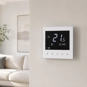
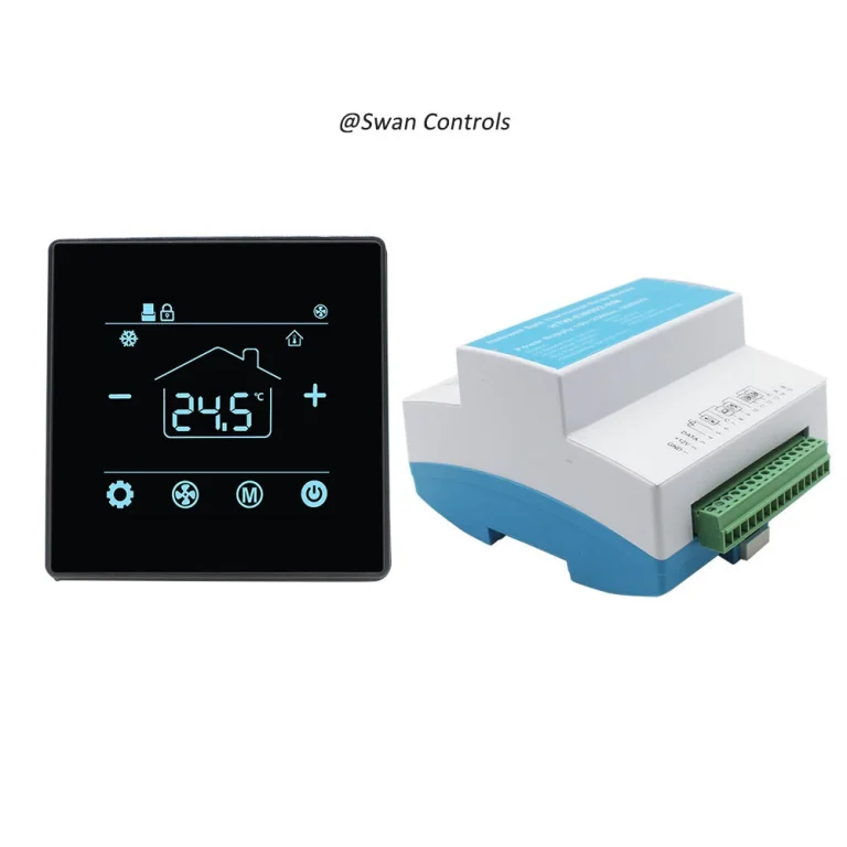
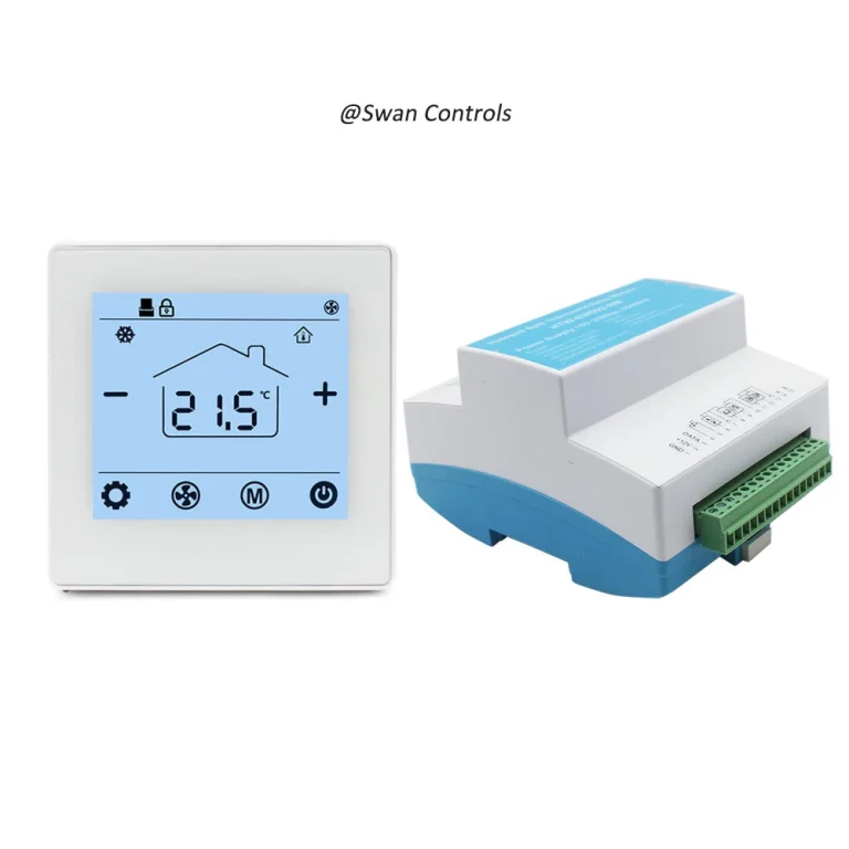
For projects where external sensing and on-off valve control both matter, we would like to recommend our model Swan Controls HTW-WF11-FC-2E , shown in picture below.

When a Floor Sensor Is Required
A floor sensor is mainly used in electric floor heating systems. It does not replace room comfort control. It protects and monitors the floor temperature.
For electric heating, the user may care about room temperature, but the floor surface and heating cable also need protection. If the floor temperature rises too high, comfort and safety issues may appear.
A room thermostat for electric floor heating should support the correct floor sensor when the project needs floor temperature limitation. It should also match the heating load.
Floor sensor matching is important when:
- Electric floor heating is installed.
- The floor material has a temperature limit.
- The buyer needs overheating protection.
- The room may heat slowly.
- The heating cable load is high.
- The project uses 16A direct control.
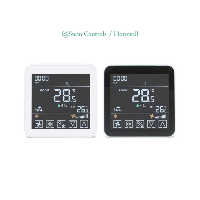
For electric underfloor heating projects, our model Swan Controls HTW-HT09-16A3 is recommended, whose design is shown in the below picture.

Matching Relay Output Correctly
Relay output is common in HVAC and heating thermostats. But relay output is not the same as every control signal.
A relay is mainly used to switch a circuit on or off. It can be used for on/off valves, fan speed control, boiler signals, or electric heating loads. However, the voltage, current, and contact type must match the equipment.
A digital thermostat with relay output should be checked for:
- Output voltage type
- Relay current rating
- Dry contact or powered output
- Fan relay capacity
- Valve relay logic
- Heating load rating
- Whether a contactor is needed
- Normally open or normally closed control
Relay output is suitable when the equipment only needs open/close or on/off control. It is not suitable when the equipment needs proportional control.
Dry Contact vs Powered Output
Dry contact and powered output are often confused.
A dry contact works like a switch. It does not supply its own voltage to the controlled equipment. The controlled device uses its own circuit, and the thermostat only opens or closes the contact.
A powered output sends voltage from the thermostat to the load. This may be suitable for some valves, fans, or heating controls, but only when the voltage and current are correct.
A room thermostat should not be connected to a boiler, valve, or control board until this point is confirmed. A boiler may need a dry contact signal. A valve actuator may need a powered signal. A heating load may need a rated relay output or a separate contactor.
Ask these questions before ordering:
- Does the equipment need dry contact?
- Does the thermostat provide powered output?
- What voltage does the actuator require?
- What is the current load?
- Is a contactor needed for larger heating loads?
- Can the supplier provide a wiring diagram?
Dry contact is often safer for interface control, while powered output is useful when the thermostat is designed to drive the connected load directly.
Matching Fan Relay and Fan Output
Fan control is a major part of FCU projects.
Traditional fan coil units often use 3-speed fan control: low, medium, and high. In this case, the controller switches different fan speed outputs. The wiring must match the fan motor and project voltage.
A digital thermostat for a standard FCU project should confirm:
- Fan voltage
- Fan speed terminals
- Relay rating
- Auto or manual fan mode
- Fan stop logic
- Fan operation in heating and cooling
- Whether fan control is direct or through an external relay
If the fan relay rating is too low, reliability issues may appear. If the fan speed wiring is wrong, the room may be noisy, slow to respond, or uncomfortable.
For simple local fan coil control, please refer to this 3-speed fan thermostat HTW-WF08-FC-2.

Matching 0–10V Output for EC Fan
EC fan control is different from traditional 3-speed relay control.
An EC fan often uses 0–10V input to control fan speed smoothly. If the project needs EC fan control, a relay-only controller is usually not suitable. The output signal must match the fan input.
A room thermostat for EC fan projects should be checked for:
- 0–10V fan output
- 24V power supply, if required
- Fan speed curve
- Minimum and maximum output
- Auto fan control logic
- Whether valve output is also 0–10V
- Whether BMS communication is needed
If this is not matched correctly, the EC fan may run at the wrong speed, fail to modulate, or create comfort and noise complaints.
For EC fan projects with 0–10V fan and valve control, please refer to this model Swan Controls HTW-WF11-FVM .
Matching Valve Output Type
Valve output is another area where buyers often make mistakes.
Some projects use simple on/off valves. Some projects use modulating valves. Some use PICV with 0–10V control. These valve types require different output signals.
A digital thermostat should match the valve actuator, not just the FCU system name.
| Valve Type | Output Needed | Common Risk |
|---|---|---|
| On/off valve | Relay or powered on/off output | Wrong voltage or wrong open/close logic |
| 3-wire valve | Specific open/close wiring | Miswired terminals |
| Modulating valve | 0–10V output | Relay-only controller cannot modulate |
| PICV actuator | Usually 0–10V control | Flow control becomes inaccurate |
| 24V valve | Correct low-voltage output or external power | Damage or no response if voltage is wrong |
For 0–10V valve or PICV projects, this model HTW-WF11-FC-MEN is suitable.
Matching Heat Pump Outputs
Heat pump systems need a different matching process.
A heat pump thermostat may need to control compressor stages, reversing valve, AUX heat, emergency heat, and fan output. The installer must confirm the control sequence before wiring.
A digital thermostat used for heat pump projects should match:
- 24V power supply
- Y1/Y2 cooling or compressor stages
- W/AUX heating output
- O/B reversing valve logic
- G fan control
- Emergency heat function
- Multi-stage heating and cooling
- Wi-Fi or app control need
The reversing valve is especially important. Some systems energise the reversing valve in cooling, while others energise it in heating. If the O/B setting is wrong, the room may heat when the user expects cooling.
For heat pump and conventional HVAC systems using 24V control and multi-stage outputs, this model HTW-MT8600 might fit.

Matching BACnet or Modbus Output Points
For BMS projects, “BACnet supported” or “Modbus supported” is not enough.
The project team should confirm what data points are available, what can be read, and what can be written. If the point list does not match the BMS requirement, the system may power on but still fail commissioning.
A room thermostat used in BMS projects should define:
- Room temperature
- Setpoint
- Mode
- Fan speed
- Valve status
- Occupancy or keycard status
- Alarm or fault status
- Device address
- Baud rate
- Read/write permission
- BACnet objects or Modbus registers
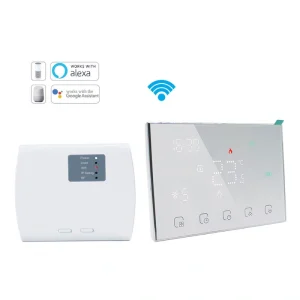
For BACnet FCU projects needing BMS integration, we would like to recommend this HTW-31-F10-2B , while for hotel FCU projects needing keycard and BACnet control, this thermostat HTW-WF11-FC-KB is suitable.
System-Based Matching Table
| Project Type | Sensor Needed | Relay or Output Type | Key Risk |
|---|---|---|---|
| Basic 2-pipe FCU | Built-in sensor | Fan relay + on/off valve | Wrong fan or valve wiring |
| Hotel FCU | Built-in or external sensor | Fan + valve + keycard + BACnet | Energy logic not matched |
| EC fan FCU | Built-in or external sensor | 0–10V fan output | Fan cannot modulate |
| PICV FCU | External sensor optional | 0–10V valve output | Valve cannot control flow |
| Heat pump system | Built-in sensor | 24V multi-stage output | O/B or AUX logic mismatch |
| Electric floor heating | Floor sensor | 16A heating relay | Overload or floor overheating |
| BMS project | Built-in or external sensor | Modbus or BACnet points | BMS cannot read/write data |
This table is useful before sample approval. It helps buyers check whether the digital thermostat matches the system input and output requirements.
Real Project Mismatch Examples
Case 1: EC Fan Project Using Relay-Only Thermostat
An office FCU project used EC fans with 0–10V speed control. During purchasing, the buyer selected a standard relay-output thermostat because the appearance and basic functions seemed suitable.
However, the EC fan required a proportional 0–10V signal instead of 3-speed relay switching. After installation, the fan could not modulate correctly and often ran at unstable or incorrect speeds.
The problem was not the fan itself, but the output mismatch between the thermostat and the controlled equipment.
Case 2: Built-In Sensor Installed in a Poor Sensing Location
A hotel project installed room thermostats near the entrance door for easier guest access. The project used built-in room sensors without considering the airflow and temperature difference near the corridor area.
After installation, guests reported that the room temperature felt different from the displayed value. The thermostat reacted too quickly whenever the door opened, even though the main occupied area deeper inside the room remained stable.
In this case, the thermostat itself worked normally, but the sensing location was not suitable for accurate room temperature control. An external room sensor would have been a better choice for this layout.
FAQ
How do I choose the right sensor for a digital thermostat?
Choose the sensor based on where the real room temperature should be measured. A built-in sensor is suitable for normal wall placement, an external sensor is better when the controller location is not ideal, and a floor sensor is needed for electric floor heating protection.
What is the difference between relay output and 0–10V output?
Relay output is mainly used for on/off switching, such as simple valves, fan speed relays, boiler signals, or heating loads. A 0–10V output provides a proportional signal and is used for EC fans, modulating valves, or PICV control.
When should I use a dry contact thermostat output?
Dry contact output should be used when the controlled equipment needs a switch signal but does not need the thermostat to supply voltage. This is common for some boiler interfaces and control boards.
Can one room thermostat support both FCU and heat pump systems?
Only if the model is designed for both applications. FCU systems usually need fan and valve control, while heat pump systems need compressor stages, reversing valve logic, AUX heat, and 24V control outputs.
What should I send to the supplier before ordering?
Send the supplier your system type, power supply, fan type, valve type, sensor requirement, load current, output signal, communication protocol, BMS point list, and sample testing plan. This helps confirm the right model before production.
Final Note / Practical Takeaway
Matching a digital thermostat with the right sensor, relay, or output type is not a small technical detail. It directly affects whether the HVAC or heating system can control the room accurately, safely, and reliably.
Sensor matching affects temperature accuracy. Relay matching affects switching safety and load handling. Output matching affects how fans, valves, boilers, heat pumps, and heating systems respond. Communication point matching affects BMS integration and commissioning.
A room thermostat should always be checked from two sides: what temperature it reads and what control signal it sends. If either side is mismatched, the system may still power on but fail to control the room correctly.
Before requesting samples or quotation, buyers should confirm the sensor location, valve type, fan control method, heating load, power supply, output signal, and communication requirement. Clear project information helps reduce installation risk, commissioning problems, customer complaints, and unnecessary replacement cost.
References / Sources
- U.S. Department of Energy, “Programmable Thermostats.” https://www.energy.gov/energysaver/programmable-thermostats
- ENERGY STAR, “Smart Thermostats.” https://www.energystar.gov/products/smart_thermostats
- ASHRAE, “Standard 55: Thermal Environmental Conditions for Human Occupancy.” https://www.ashrae.org/technical-resources/bookstore/standard-55-thermal-environmental-conditions-for-human-occupancy
- ASHRAE, “BACnet™, the ASHRAE Building Automation and Control Networking Protocol.” https://www.ashrae.org/technical-resources/bookstore/bacnet
- BACnet International, “About the BACnet Standard.” https://bacnet.org/about-bacnet-standard/
- Modbus Organization, “Modbus Organization.” https://www.modbus.org/
- International Energy Agency, “Space Cooling.” https://www.iea.org/energy-system/buildings/space-cooling
- International Energy Agency, “The Future of Cooling.” https://www.iea.org/reports/the-future-of-cooling
- U.S. Energy Information Administration, “Use of Energy Explained: Energy Use in Homes.” https://www.eia.gov/energyexplained/use-of-energy/homes.php
- ENERGY STAR, “Air Source Heat Pumps.” https://www.energystar.gov/products/air_source_heat_pumps
Copyright © Swan Controls © Hotowell. All rights reserved. This article is written and published by Swan Controls, an affiliate of Hotowell. The content may not be copied, rewritten, or reused for commercial purposes without permission. For product selection or project support, please feel free to get in touch with us directly.